
2006 500 Fuse Diagram
2006 500 Fuse Diagram
This 2006 500 Fuse Diagram shows two fuse boxes; the Battery Junction Box/Power Distribution Box located under the hood and the Smart Junction Box/Passenger Compartment Fuse Panel located under the dash to the left of the steering wheel, near the brake pedal.
There’s lots more information on this site for your vehicle.
To find fuse diagrams, click here
To find Relay locations, click here
To find Sensor Locations, click here
To find Module Locations, click here
To find Switch Locations, click here
To find Firing Order, click here
To find the most common trouble codes and fixes for your vehicle, click here
2006 500 Fuse Diagram Battery Junction Box
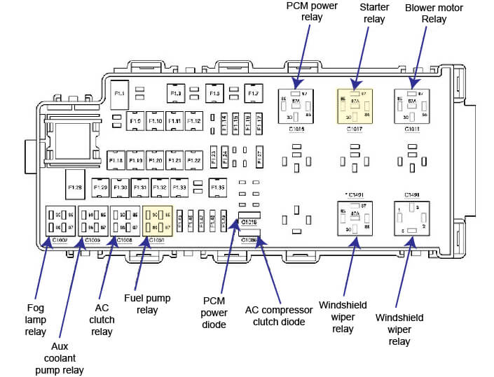
2006 Ford 500 Fuse Diagram Battery Junction Box
1.1 80 F2.1, F2.2, F2.3, F2.4, F2.5
1.2 – not used
1.3 50 Windshield wiper relay
1.4 – not used
1.5 20 Roof opening panel module
1.6 – not used
1.7 60 Engine cooling fan motor
1.8 – not used
1.9 40 ABS control module
1.10 30 Starter relay
1.11 30 PCM power relay
1.12 20 ABS control module
1.13 – not used
1.14 20 Power point, rear
1.15 15 CVT module (7000), 6-speed automatic transaxle module
1.16 20 Power point, console
1.17 10 Generator
1.18 40 Smart Junction Box (SJB)
1.19 20 Headlamp, right
1.20 40 Heated backlight relay
1.21 30 Seat adjust switch, passenger side front
1.22 30 Heated seat module, driver side front (14C724), Heated seat module, passenger side front
1.23 15 Fog lamp relay
1.24 10 A/C clutch relay
1.25 – not used
1.26 – not used
1.27 15 Fuel pump relay
1.28 80 F2.6, F2.7, F2.9, F2.10, F2.11, F2.25
1.29 30 Power window motor, driver side front
1.30 20 Headlamp, left
1.31 30 Auxiliary relay box 1, Auxiliary coolant pump relay
1.32 30 Driver seat module, Seat adjust switch, driver side front
1.33 30 Ignition switch
1.34 – not used
1.35 40 Blower motor relay
1.36 – not used
1.37 – not used
1.38 – not used
1.45 30 Windshield wiper motor
1.46 5 Heated Positive Crankcase Ventilation (PCV) valve
1.47 25 Rear wiper motor assembly
1.48 10 Vapor management valve, EVAP canister vent control solenoid, A/C clutch relay, Heated Oxygen Sensor (HO2S) #11, Heated Oxygen Sensor (HO2S) #12, Heated Oxygen Sensor (HO2S) #21, Heated Oxygen Sensor (HO2S) #22, EGR system module, CVT module (7000), 6-speed automatic transaxle module
1.49 15 Mass Air Flow (MAF) sensor, Powertrain Control Module (PCM), Fuel injector 1, Fuel injector 2, Fuel injector 3, Fuel injector 4, Fuel injector 5, Fuel injector 6, Coil On Plug (COP) 1, Coil On Plug (COP) 2, Coil On Plug (COP) 3, Coil On Plug (COP) 4, Coil On Plug (COP) 5, Coil On Plug (COP) 6, ignition transformer capacitor
2006 500 Fuse Diagram Smart Junction Box
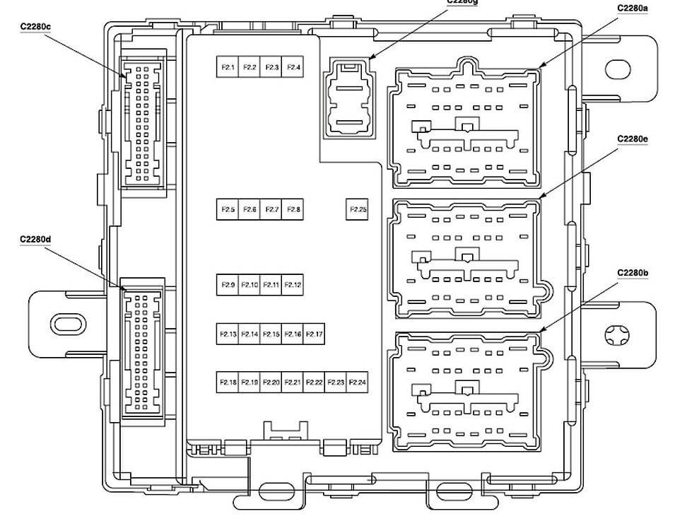
2006 Ford 500 Fuse Diagram Smart Junction Box
2.1 20 High beam relay
2.2 15 Courtesy lamp relay, Battery saver relay, Accessory delay relay
2.3 25 Door lock relay, Door unlock relay, Driver door unlock relay, Decklid relay
2.4 15 Adjustable pedal switch
2.5 20 Horn
2.6 20 Subwoofer amplifier
2.7 7.5 Electronic Automatic Temperature Control (EATC) module, Function selector switch assembly(Manual A/C), Powertrain Control Module (PCM), Clock (15000), Instrument cluster
2.8 15 Park/turn lamp, left front, Park/turn lamp, right front, Side lamp, left front, Side lamp, right front, Lamp assembly, left rear, Lamp assembly, right rear, License lamps, License plate lamp, left, License plate lamp, right
2.9 20 Data Link Connector (DLC), Power point, instrument panel
2.10 7.5 Exterior rear view mirror switch, Seat adjust switch, driver side front, Driver seat module
2.11 20 Rear Seat Entertainment (RSE) module, Radio
2.12 10 Lamp assembly, left rear, Lamp assembly, right rear, Electrochromatic inside mirror unit, Parking Aid Module (PAM
2.13 7.5 Radio
2.14 7.5 Starter relay, Powertrain Control Module (PCM)
2.15 10 Door lock switch, driver side, Door lock switch, passenger side, Power window motor, driver side front, Auxiliary function selector switch assembly, rear, Roof opening panel module, Radio
2.16 10 Function selector switch assembly, Exterior rear view mirror, right, Exterior rear view mirror, left
2.17 30 Rear window defrost grid
2.18 10 Passive anti-theft transceiver, Brake pedal position switch, Redundant pedal switch, PCM power diode, PCM power relay, Fuel pump relay, F1.46
2.19 10 Parking Aid Module (PAM), Heated seat module, driver side front, Heated seat module, passenger side front, Traction assist/Parking aid disable switch, Differential Electronic Module (DEM), ABS control module
2.20 7.5 Function selector switch assembly, Electronic Automatic Temperature Control (EATC) module, Instrument cluster
2.21 7.5 Restraints control module
2.22 7.5 Electronic compass, Electrochromatic inside mirror unit, Auxiliary relay box 1, Auxiliary relay box 2, Auxiliary relay box 3
2.23 7.5 Instrument cluster, Blower motor relay, Windshield wiper relay
2.24 7.5 Passenger Air bag Deactivation (PAD) indicator (14B268), Occupant Classification Sensor (OCS)
2.25 30 c.b. Accessory delay relay
Posted on by Rick Muscoplat