
2006 Crown Victoria Fuse Diagram
2006 Crown Victoria Fuse Diagram
2006 Crown Victoria Fuse Diagram shows two fuse boxes; the Battery Junction Box/Power Distribution Box located under the hood and the Smart Junction Box/Passenger Compartment Fuse Panel located under the dash to the left of the steering wheel, near the brake pedal.
There’s lots more information on this site for your vehicle.
To find fuse diagrams, click here
To find Relay locations, click here
To find Sensor Locations, click here
To find Module Locations, click here
To find Switch Locations, click here
To find Firing Order, click here
To find the most common trouble codes and fixes for your vehicle, click here
2006 Crown Victoria Fuse Diagram Battery Junction Box
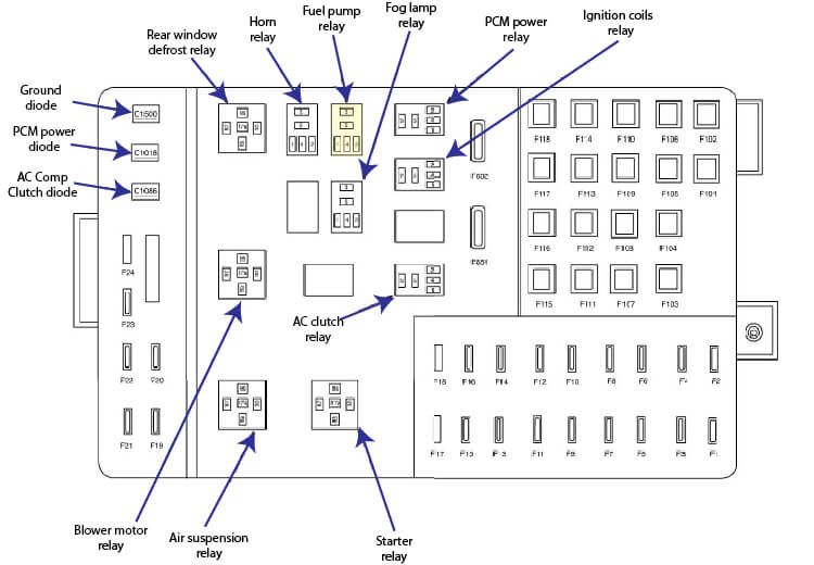
2006 Ford Crown Victoria Battery Junction Box
1 25 Ignition switch
2 25 Ignition switch
3 10 Powertrain Control Module (PCM
4 20 Fuel pump relay
5 10 Air suspension module, Variable Assist Power Steering (VAPS) module
6 15 Generator
7 30 PCM power relay
8 20 Driver Door Module
9 15 Ignition coils relay
10 20 Horn relay
11 15 A/C clutch relay
12 25 Subwoofer amplifier. Radio
13 20 Power point
14 20 Brake pedal position switch
15 20 Heated seal module, driver side front, Heated seat module, passenger side front
16 15 (1) 25 Fog lamp relay (1) Emergency flasher relay
17 – not used
18 – not used
19 15 Fuel injector 1 , Fuel injector 2 , Fuel injector 3 , Fuel injector 4 , Fuel injector 5 , Fuel injector 6 , Fuel injector 7 . Fuel injector 8
F20 15 Powertrain Control Module (PCM), Mass Air Flow (MAF) sensor
21 15 A/C clutch relay. Evaporative emission (EVAP) canister vent valve. Vapor management valve. Heated Oxygen Sensor (HO2S) #11. Heated Oxygen Sensor (HO2S) #12. Heated Oxygen Sensor (HO2S) #21, Heated Oxygen Sensor (HO2S) #22, 4R70W transmission, EGR System Module (ESM), Heated PCV
22 20 ends in harness
23 20 ends in harness
24 – not used
101 40 Blower motor relay
102 50 Engine cooling fan module
103 50 Central Junction Box (CJB)
104 40 Central Junction Box (CJB)
105 30 Starter relay
106 40 ABS control module
107 40 Rear window defrost relay
108 20 Roof opening panel unit, Overhead console, Spot lamp. LH side, Spot lamp, RH side
109 20 ABS control module
110 30 Windshield wiper motor
111 50 ends in harness, Police accessory connector
112 30 (1) 40 Air suspension compressor relay. Police power relay
113 50 ends in harness. Police C-pillar connector
114 50 Police light bar relay/fuse center, ends in harness
115 50 Police auxiliary junction box, rear. Police light bar relay/fuse center, ends in harness
116 50 Police glove box relay/fuse center
117 50 Police option fuse holder, ends in harness
118 50 Police auxiliary junction box, rear. Police trunk relay/fuse center
601 20CB Seat adjust switch, driver side front. Seat adjust switch, passenger side front, Lumbar adjust switch, driver side. Lumbar adjust switch, passenger side, Decklid (Police only)
602 20CB Accessory relay
2006 Crown Victoria Fuse Diagram Central Junction Box
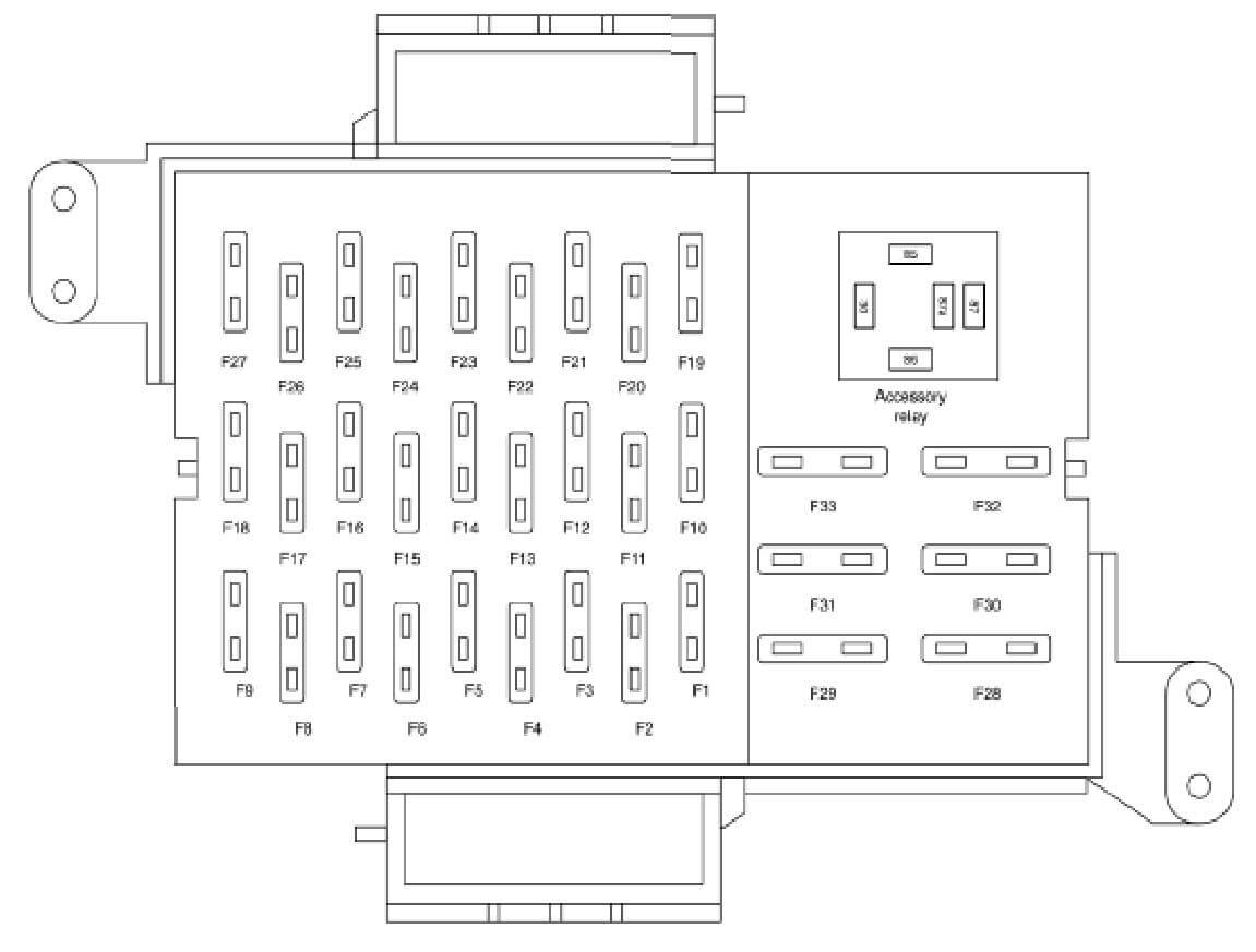
2006 Ford Crown Victoria Central Junction Box
1 15 Lighting control module, Instrument cluster, Taxi roof lamp switch
2 10 Function selector switch assembly, Electronic Automatic Temperature Control (EATC) module. Blower motor relay
3 10 Electronic Automatic Temperature Control (EATC) module
4 10 ABS control module. ABS control module. Air suspension module, VAPS
5 10 Deactivation switch, Brake pedal position switch
6 10 Instrument cluster
7 15 Lighting control module
8 10 Lighting control module
9 10 Lighting control module
10 5 ends in harness, Radio
11 10 Accessory relay. Police power relay
12 10 Digital Transmission Range (DTR) sensor
13 10 Windshield wiper motor
14 10 Brake shift interlock
15 7.5 Lighting control module. Seat heater switch, driver side, Door lock switch, driver side. Door lock switch, passenger side. Seat heater switch, passenger side. Overhead console, Electrochromatic inside mirror unit, Roof opening panel unit
16 15 Multifunction switch
17 10 Radio. Antenna module
18 10 Temperature blend door actuator, Function selector switch assembly, Heated seat module, driver side front. Heated seat module, passenger side front
19 10 Lighting control module
20 10 Digital Transmission Range (DTR) sensor
21 10 Headlamp, right (13008), Lighting control module
22 10 Passenger Air bag Deactivation (PAD) indicator. Restraints control module. Occupant classification sensor module
23 15 Multifunction switch, Lighting control module
24 10 Passive anti-theft transceiver, PCM power diode
25 10 Autolamp sensor, Adjustable pedal switch, Exterior rear view mirror switch. Door lock switch, driver side. Door lock switch, passenger side. Driver door module. Luggage compartment lid release switch 1
26 10 Instrument cluster, Lighting control module. Rear window detrost relay. Transmission control switch
27 20 Data Link Connector (DLC). Cigar lighter, front
28 7.5 High mounted stoplamp
29 15 Radio
30 15 Multifunction switch
31 15/(1)20 Multifunction switch
32 10 Rear window defrost switch, Exterior rear view mirror. left, Exterior rear view mirror, right
33 10 Fire suppression module. Fire suppression manual switch
Police
(1)
Posted on by Rick Muscoplat