
2006 Freestar Fuse Diagram
2006 Freestar Fuse Diagram Montery Fuse Diagram
This 2006 Freestar Fuse Diagram shows two fuse boxes; the Bussed Electrical Center located under the hood and the Smart Junction Box/Passenger Compartment Fuse Panel located under the dash to the left of the steering wheel. Ford also includes a relay center.
There’s lots more information on this site for your vehicle.
To find fuse diagrams, click here
To find Relay locations, click here
To find Sensor Locations, click here
To find Module Locations, click here
To find Switch Locations, click here
To find Firing Order, click here
To find the most common trouble codes and fixes for your vehicle, click here
2006 Freestar Fuse Diagram Bussed Electrical Center
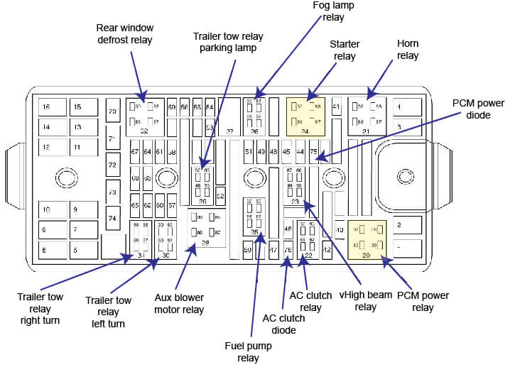
2007 Ford Freestar Fuse Diagram Bussed Electrical Center
1 – not used
2 30A Engine cooling fan relay 2
3 30A Engine cooling fan relay 1
4 30A Starter relay
5 30A Module, power sliding door. RH side
6 30A Accessory delay relay 2
7 30A Auxiliary blower motor relay
8 40A ABS control module
9 30A Power liftgate module
10 30A Accessory delay relay 1
11 30A Seat adjust switch, driver side front, Driver seat module, Heated seat module, driver side front, Climate controlled seat module, driver side
12 40A ABS control module
13 40A Rear window defrost relay
14 30A Front blower motor relay
15 30A Seat adjust switch, passenger side front, Heated seat module, passenger side front, Climate controlled seat module, passenger side
16 30A Module, power sliding door, LH side Minifuse
MINI FUSES
40 15A A/C clutch relay, Intake Manifold Runner Control (IMRC) module, Positive crankcase ventilation heater, Heated Oxygen Sensor (HO2S) #12, Heated Oxygen Sensor (HO2S) #22, EVAP canister purge valve, Heated Oxygen Sensor (HO2S) #11, Heated Oxygen Sensor (HO2S) #21, AX4S/4F50N Transmission
41 25A Horn relay
42 10A A/C clutch relay
43 15A Engine cooling fan relay 1, Engine cooling fan relay 2, Engine cooling fan relay 3, Engine cooling fan relay 4, Engine cooling fan relay 5, Fuel injectors, EGR system module, Powertrain Control Module (PCM), Idle Air Control (IAC) valve, Mass Air Flow (MAF) sensor, Ignition coil
44 10A Positive crankcase ventilation heater
45 15A High beam relay
46 20A Trailer tow relay, right turn, Trailer tow relay, left turn
47 15A Fuel pump relay, Inertia Fuel Shutoff (IFS) switch
48 15A Fog lamp relay
49 10A Powertain Control Module (PCM), Evaporative emission (EVAP) canister vent valve
50 10A Generator
51 10A Adjustable pedal switch, Seat adjust switch, driver side front, Driver seat module
52 20A Trailer tow relay, parking lamp
53 10A Exterior rear view mirror, left, Exterior rear view mirror, right, (Heating element)
54 30A Windshield wiper motor
55 25A Rear wiper motor assembly
56 30A Audio unit
57 – not used
58 30A High mounted stoplamp, License lamps, Data Link Connector (DLC), Interior lamps, Switch illumination, Smart Junction Box (SJB), Fuses F2.8, F2.9, F2.10, F2.11
59 20A Audio unit, base audio
60 30A Reversing lamps, Door unlock relay, Door lock relay, Driver door unlock relay
61 – not used Parking lamp, right front, Headlamp, right, Park/turn lamp, left front, Park/stop/turn lamp, left rear. Courtesy lamp, left footwell, Courtesy lamp, right footwell, Sliding door entry lamp, left, Sliding door entry lamp, right, Exterior rear view mirror, left, Overhead console, DVD player. Rear Integrated Control Panel (RICP), Main light switch, Electronic Manual Temperature Control (EMTC) module, Clock, Instrument cluster, Message center switch, Smart Junction Box (SJB), Fuse F2.15
63 20A Power point, instrument panel, Cigar lighter, front
64 20A Ignition switch
65 30A Headlamp, left, Parking lamp, left front, Park/turn lamp, right front, Park/stop/turn lamp, right rear, Exterior rear view mirror, right, Vanity mirror lamp, left, Vanity mirror lamp, right, Interior lamps, Electronic Manual Temperature Control (EMTC) module
66 20A Power point, C pillar, Power point, rear
67 20A Ignition switch
2006 Freestar Fuse Diagram Smart Junction Box
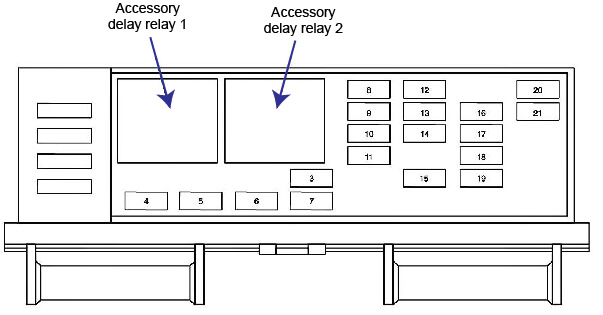
2007 Ford Freestar Fuse Diagram Smart Junction Box
3 10A Windshield wiper motor
4 5A Exterior rear view mirror switch
5 20A Power quarter window switch, Audio unit
6 5A Door lock switch, driver side, Door lock switch, passenger side, Memory set switch, Exterior rear view mirror switch
7 10A Rear wiper motor assembly
8 10A Instrument cluster, Electronic Automatic Temperature Control (EATC) module, Electronic Manual Temperature Control (EMTC) module, DVD player
9 10A Autolamp/Sunload sensor
10 5A Rear Integrated Control Panel (RICP)
11 5A Auxiliary blower speed relay 1, Auxiliary blower speed relay 2, Power liftgate module, Module, power sliding door, LH side, Module, power sliding door, RH side, Data Link Connector (DLC), Clock
12 5A Electronic Manual Temperature Control (EMTC) module, Brake shift interlock, Electronic Automatic Temperature Control (EATC) module
13 5A Overhead console, Heated seat module, driver side front, Heated seat module, passenger side front, Parking Aid Module (PAM), Power liftgate module, Module, power sliding door, LH side, Module, power sliding door, RH side, Climate controlled seat module
14 5A Front blower motor relay, Rear window defrost relay
15 10A Brake pedal position switch
16 5A Steering position sensor, Overhead console, Electrochromatic inside mirror unit, Instrument cluster
17 10A Restraints control module, Power quarter window switch, Occupant classification sensor module
18 10A ABS control module, Brake pressure switch, Speed control servo
19 5A Passive anti-theft transceiver module, Instrument cluster, PCM power diode
20 10A Power liftgate module, Audio unit
21 10A Digital Transmission Range (DTR) sensor
2006 Freestar Fuse Diagram Auxilliary Relay Center
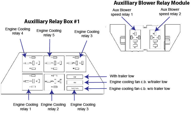
2007 Ford Freestar Fuse Diagram Aux relays