
2006 Taurus Fuse Diagram
2006 Taurus Fuse Diagrams
Here are the 2006 Taurus Fuse Diagram for Battery Junction Box, Smart Junction Box and Relay Center Box. The Battery Junction Box Center is located in the center of engine compartment behind the radiator. The Smart Junction Box is located on the left underside of dash. The Relay Center Box is located on left front of engine compartment near ABS control module.
There’s lots more information on this site for your vehicle.
To find fuse diagrams, click here
To find Relay locations, click here
To find Sensor Locations, click here
To find Module Locations, click here
To find Switch Locations, click here
To find Firing Order, click here
To find the most common trouble codes and fixes for your vehicle, click here
2006 Taurus Fuse Diagrams for Battery Junction Box
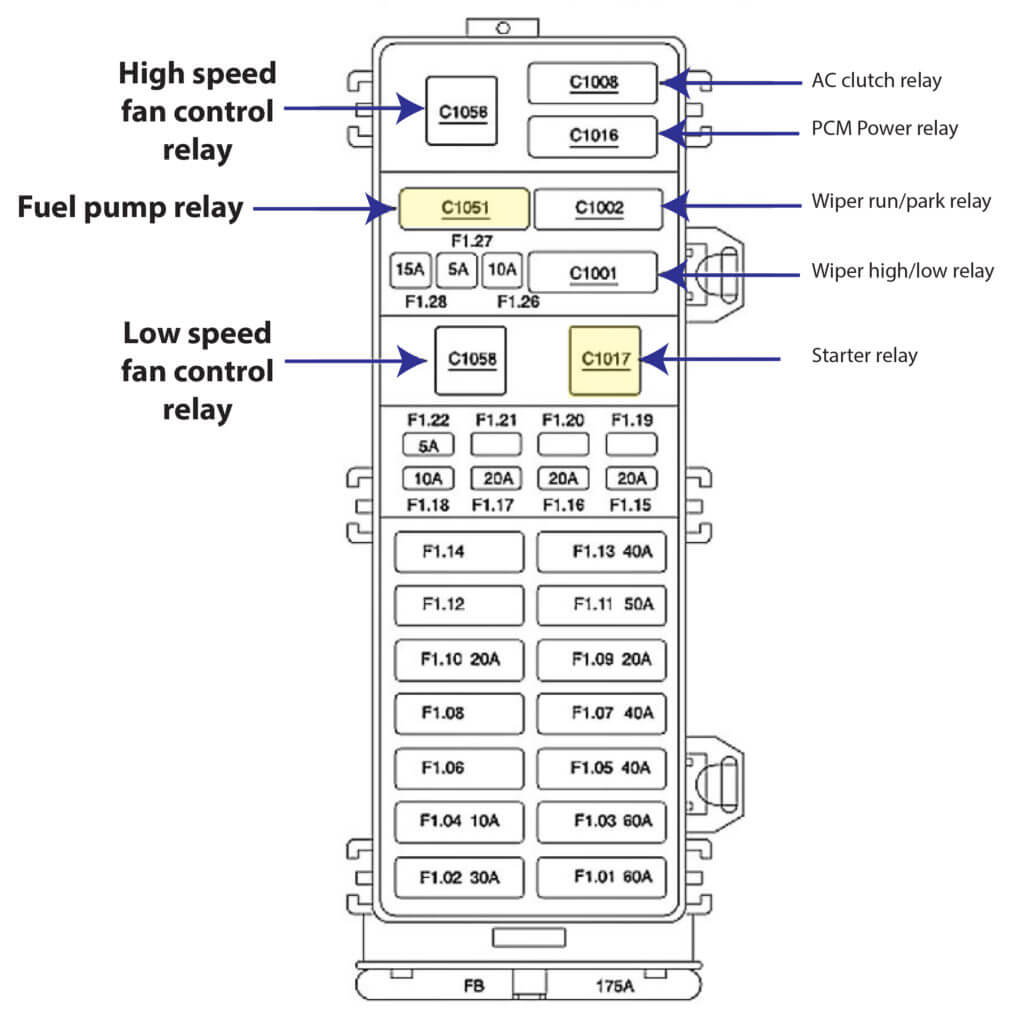
2006 Ford Taurus Fuse Diagram Battery Junction Box
FB 175 Battery Junction Box (BJB) (14A003), Generator (10300)
F1.01 60 Smart Junction Box (SJB) (14B476)
F1.02 30 PCM power relay
F1.03 60 Smart Junction Box (SJB) (14B476)
F1.04 10 Engine cooling fan motor 1 (BC607)
F1.05 40 Engine cooling fan motor
F1.06 – not used
F1.07 40 Starter relay (11450), Ignition switch (11572)
F1.08 – not used
F1.09 20 Engine cooling fan brake relay
F1.10 20 Engine cooling fan motor 2 (8C607)
F1.11 50 Rear window defrost relay 2
F1.12 – not used
F1.13 40 ABS control module (2C346)
F1.14 – not used
F1.15 20 ABS control module (2C346)
F1.16 20 Fuel pump relay
F1.17 20 Rear Control Unit (RCU) (18C851), CD changer (18C630)
F1.18 10 Powertrain Control Module (PCM) (12A650), A/C clutch relay, Idle Air Control (IAC)
valve (9F715)
F1.19 – not used
F1.20 – not used
F1.21 – not used
F1.22 5 Positive crankcase ventilation heater
F1.26 10 Generator (10300)
F1.27 5 Rear Control Unit (RCU) (18C851)
F1.28 15 AX4S/4F50N Transmission (7000), A/C clutch relay, Evaporative emission (EVAP)
2006 Taurus Fuse Diagrams for Smart Junction Box
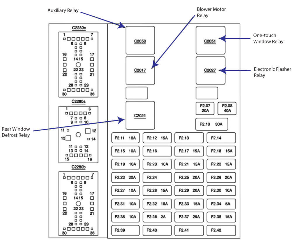
2010 Taurus Fuse Box Diagram Smart Junction Box
F2.07 20 Rear window defrost relay
F2.08 40 Blower motor relay
F2.10 30 c.b. Accessory relay, Seat adjust switch
F2.11 10 Headlamp, left (13008), Low beam
F2.12 15 Headlamp, right (13008), Headlamp, left (13008), High beams
F2.13 – not used
F2.14 – not used
F2.15 10 Headlamp, right (13008), Low beam
F2.16 – not used
F2.17 15 Deactivator switch (9F924), Brake pedal position switch (13480)
F2.18 15 Autolamp park relay, Main light switch (11654) canister vent valve (9F945), Oxygen sensor (O2S), Mass Air Flow (MAF) sensor (12B579)
F2.19 10 Defrost indicator, Heated mirrors
F2.20 10 Restraints control module (14B321), Seat weight sensor module (14B422)
F2.21 15 Digital Transmission Range (DTR) sensor (7F293) (Starter relay circuit)
F2.22 15 Windshield washer relay, Integrated control panel (18C858), Electrochromatic inside mirror
unit (17700), Instrument cluster (10849), Smart Junction Box (SJB) (14B476), Hot in Run
or Acc
F2.23 30 Wiper run/park relay, Wiper high/low relay, Windshield wiper motor (17500)
F2.24 – not used
F2.25 20 Cigar lighter, front (15055)
F2.26 20 Door lock relay, Door unlock relay, Driver door unlock relay, Luggage compartment lid release relay
F2.27 10 Rear window defrost relay, Speed control servo (9C735), ABS control module (2C346), Brake shift interlock (3Z719), Traction control switch (2C355), Temperature blend door actuator (19E616), Function selector switch assembly (19B888)
F2.28 15 Digital Transmission Range (DTR) sensor (7F293) (Reverse signal), Multifunction switch (13K359) (Turn signals)
F2.29 20 Power point (19N236)
F2.30 10 Interior lamps relay, Battery saver relay, Luggage compartment lamp (13A756), Exterior rear view mirror switch (17B676), Glove box lamp (14413)
F2.31 10 Remote Climate Control (RCC) module (18C612), Blower motor relay, Integrated control panel (18C858), A/C clutch cycling pressure switch (19D594)
F2.32 10 Instrument cluster (10849), Integrated control panel (18C858), Flexible fuel sensor module (14A069), Smart Junction Box (SJB) (14B476), Hot in Start or Run, Passenger Air bag Deactivation (PAD) indicator
F2.33 15 Remote Climate Control (RCC) module (18C612), Instrument cluster (10849), Multifunction switch (13K359), Integrated control panel (18C858), Smart Junction Box (SJB) (14B476) B+
F2.34 5 Smart Junction Box (SJB) (14B476), Hot in Start
F2.35 10 Main light switch (11654) to Illumination
F2.36 2 PCM power relay
F2.37 25 Autolamp headlamp relay, Multifunction switch (13K359), DRL
F2.38 15 Data Link Connector (DLC) (14489), Horn relay
F2.39 – not used
F2.40 – not used
F2.41 – not used
F2.42 – not used
2006 Taurus Fuse Diagrams for Relay Center Box
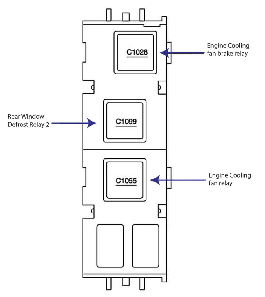
2010 Ford Taurus Fuse Box Diagram Relay Center Box