
Crankshaft position sensor code
How to deal with a crankshaft position sensor code
Chances are you’re here because you have a crankshaft position sensor code. But if you came here to find out what a crankshaft sensor is or how it works, I’ll cover that too. I’ll also discuss the differences in crankshaft sensor trouble codes. I’ll start with some background on what a crankshaft position sensor does, how it works and then I’ll get in to how to diagnose and replace. If you know that, skip to the bottom of the article.
What is a crankshaft position sensor and why does an engine need one?
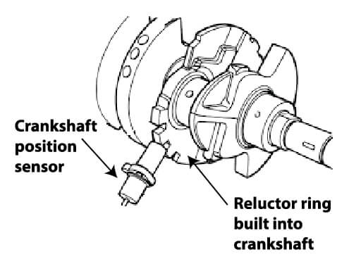
The engine control module (ECM) or powertrain control module (PCM) in your car controls when fuel injectors deliver fuel and spark to each cylinder, so it has to know the exact position of each piston in relation to the valves. Since all the pistons are driven by the crankshaft, knowing the exact position of the crankshaft makes the most sense and car makers monitor its position using a 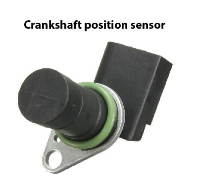 crankshaft position sensor and a notched ring mounted at the front of or inside the engine.
Timing the ignition spark in relation to the piston position is critical to obtaining the most optimal burn cycle that’ll deliver the most power with the lowest emissions. The spark must be initiated before the piston reaches the top of its travel, referred to as top dead center (TDC). Why before? Because it takes some time for the combustion event to build, so it’s timed to reach peak power AFTER the piston reaches TDC, when the piston is starting its downward power stroke.
In the old days, the ignition function was performed by the distributor. The distributor gear meshed with the camshaft and spark timing was set using a strobe light  pointed at the harmonic balancer pulley at the front of the engine. At idle, it was common to set spark timing at around 10° before top dead center (BTDC). In other words, the crankshaft had rotated 350° and was at 10° before reaching the 0° mark.
Older engines relied on either a timing chain or timing gears to synchronize the camshaft to the crankshaft. Engineers knew that timing chains could wear and stretch and timing gears could develop wear slop as they aged  or if the owner neglected oil change intervals, but they didn’t have any way to gauge how much wear had occurred. So accepted the fact that distributor spark timing could be off a bit in relation to actual crankshaft position. The difference resulted in lower power and increased emissions.
Fuel delivery was even more of a guessing game. Engines relied on carburetors to atomize gas based on airflow through the carburetor’s venture. Airflow was based on engine RPM and the degree of throttle plate opening demanded by the driver. However, carburetion is a crude way to deliver fuel because it can’t take engine and air temperature, air density or atmospheric pressure into account. As a result, carburetors often delivered too little or too much fuel to the cylinders.
Then the rules changed. Engines had to become more fuel efficient and produce fewer emissions. That drove engineers to move away from carburetors and use fuel injectors and eventually to discontinue the use of distributors. It also drove the move to overhead cam engines with multiple intake and exhaust valves per cylinder. To span the increased distance between the crankshaft and camshafts, car makers changed to rubber timing belts in some cases and much longer timing chains in others, making precise timing even more critical. To replace distributors, car makers switched to coil-on-plug (COP) or distributorless (DIS) ignition coils.
The ECM/PCM controlled when fuel injectors fired, but the early systems relied on separate ignition module to fire the spark plugs. Eventually, both functions were integrated into the ECM/PCM. However, car makers still needed a way to time the spark to the exact position of the crankshaft. Enter the crankshaft position sensor and camshaft position sensor.
How does a crankshaft position sensor work?
There are two types of crankshaft position sensors and camshaft position sensors used in modern engines:
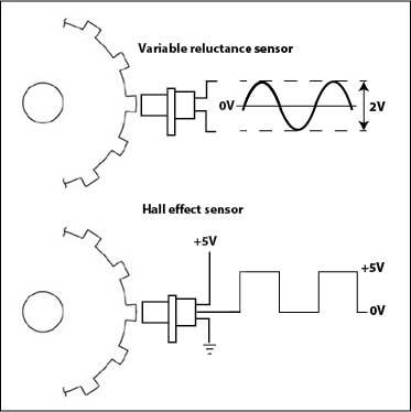
• Variable reluctance
• Hall-effect sensors
Variable reluctance sensors are stationary and generate a low AC voltage as a notched “reluctor” ring rotates a set distance away. Hall effect sensors are also stationary. They’re actually solid state devices that need power to operate and generate a digital pulse as they sense the presence of teeth on a rotating disc or “interrupter” ring.
Whether the car maker uses a reluctor or interrupter ring, there’s 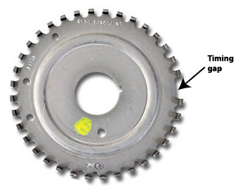 always at least one gap in the tooth spacing. The ECM/PCM rely on the gap to sense when the crankshaft or camshaft have completed a full revolution. Without the gap, the computer would have no way of sensing the number of revolutions. That’s important because the crankshaft rotates twice to one rotation of the camshaft.
Why can’t the computer fire the injectors and the spark using just the crankshaft position sensor? Simple, one sensor can’t account for timing belt or timing chain wear.
Symptoms of a failing crankshaft position sensor
• Cranks but won’t fire up. If the ECM/PCM can’t get a good signal from the sensor, it won’t provide spark, and in some cases won’t supply fuel.
• Cranks and starts intermittently. Engine starts sometimes but not others.
• Intermittent stalling
A dropped signal from the crankshaft sensor will cause the ECM/PCM to stop providing spark and/or fuel. This is often caused by a faulty wiring connection and is sometimes heat or vibration related. If you notice this going over bumps, check the wiring harness to the sensor for chaffing.
• Check Engine Light comes on and you have a crankshaft position sensor code
What are common crankshaft position sensor codes?
P0016 Crankshaft Position Camshaft Position Correlation (Bank 1 Sensor A)
P0017 Crankshaft Position Camshaft Position Correlation (Bank 1 Sensor B)
P0018 Crankshaft Position Camshaft Position Correlation (Bank 2 Sensor A)
P0019 Crankshaft Position Camshaft Position Correlation (Bank 2 Sensor B)
This first set of generic crankshaft position sensor codes talk about a correlation problem. What’s going on here is that the ECM/PCM has determined that the signals it’s receiving from the crankshaft position sensor and the camshaft position sensor don’t make sense. The A and B symbols represent those engines that incorporate multiple sensor on a single bank (for “V” style engines). Bank 1 is always the bank housing cylinder number one.
Correlation crankshaft sensor codes are usually set if the timing belt or chain is incorrect (set wrong, stretched, etc) enough to cause the camshaft to be out of synch with the crankshaft, or if the reluctor ring is cracked, had a missing tooth or rust formation. If you have these codes, start by checking the air gap between the sensors and the reluctor or interruptor ring. Also check for debris on either component. Then check the condition of the timing chain or belt.
Crankshaft position sensor circuit related codes
P0335 Crankshaft Position Sensor A Circuit Malfunction
P0336 Crankshaft Position Sensor A Circuit Range/Performance
P0337 Crankshaft Position Sensor A Circuit Low Input
P0338 Crankshaft Position Sensor A Circuit High Input
P0339 Crankshaft Position Sensor A Circuit Intermittent
P0340 Camshaft Position Sensor Circuit Malfunction
P0341 Camshaft Position Sensor Circuit Range/Performance
P0342 Camshaft Position Sensor Circuit Low Input
P0343 Camshaft Position Sensor Circuit High Input
P0344 Camshaft Position Sensor Circuit Intermittent
These are also generic codes and refer to the circuit reading the ECM/PCM is seeing. A high/low reading can be caused by an incorrect gap between the sensor and the reluctor ring or a power or grounding problem (mostly associated with Hall effect sensors). Do NOT automatically assume the sensor is bad. That can cause you to replace a perfectly good sensor. If your crankshaft position sensor has three wires, it’s usually a Hall effect type. Always check for good ground and a 5-volt reference voltage coming to the sensor (get a wiring diagram). If you see a reference voltage and get good ground and the interruptor ring is in good shape and the gap is correct, THEN you can suspect a bad sensor.
One other tip: Many Ford vehicles offer a visual check of the crankshaft position sensor. Here’s how it works. Turn the key to the ON/RUN position. The check engine or service engine soon light should be lit (that’s normal–it’s called a bulb check). Then turn the key to START and watch the check engine light. It should go out to indicate the ECM/PCM is receiving a crankshaft position sensor signal. If the light stays on and the engine doesn’t start, chances are the sensor is bad. This doesn’t apply to all makes and models.
How to replace a crankshaft position sensor
Most sensors are mounted to the front of the engine near the harmonic balancer pulley. Disconnect the electrical connector, then remove the retaining bolt(s). Reverse to install following the proper gapping procedure. If the air gap is wrong, the engine may not start or will start but run rough. If the sensor has an O-ring, lubricate it with motor oil before reinstalling the sensor. Make sure the silicone sealing ring is in place on the electrical connector before reconnecting.
©, 2016 Rick Muscoplat
Posted on by Rick Muscoplat