
2006 F150 Fuse Diagram: Exploring the Fuse Boxes
2006 F150 Fuse Diagram: Find the correct fuse for the circuit you’re working on
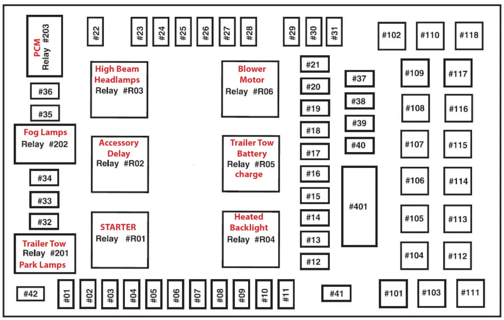
This 2006 F150 Fuse Diagram shows a Passenger Compartment Fuse Panel and an Auxiliary Relay Box.
To learn more about automotive fuses, see this article
To learn how to check a fuse visually or without removing it, see this article
2006 F150 Fuse Diagram Cabin Fuse Box/Central Junction Box/Power Distribution Box
The cabin fuse box is located under the dash on the right-hand (passenger) side of the instrument panel. Remove the trim panel and fuse box cover to access the fuses. To remove the fuse box cover, place a finger behind the PULL tab and your thumb above the PULL tab. Then, pull the cover off.
How to find your fuse and the devices served by that fuse
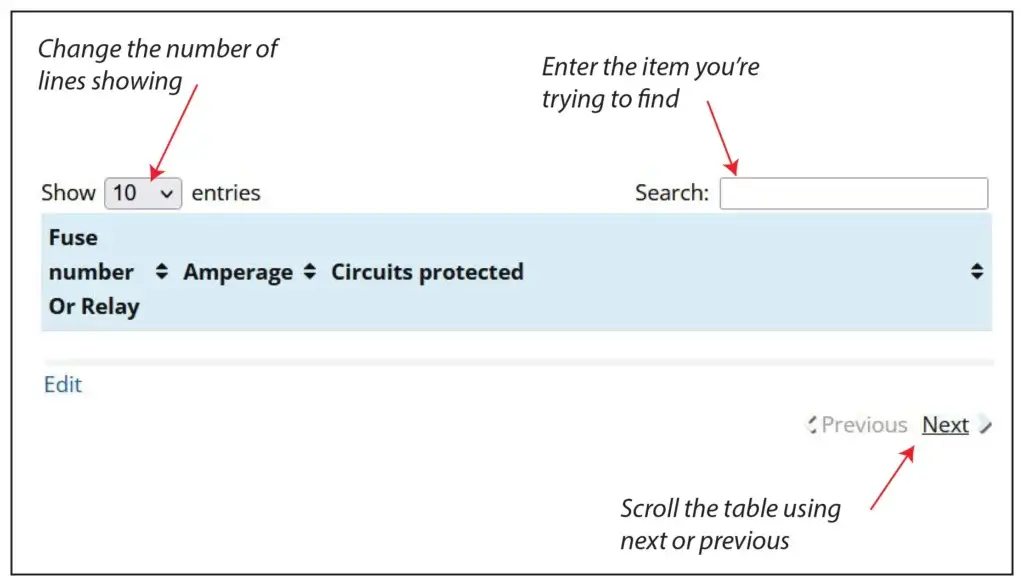
There are 71 fuse and relay slots in the Cabin Power Distribution Box. The chart shows only 10 to speed up load time. Here’s how to find the fuse and circuit you want.
1) Change the number of entries showing (in the Show Entries Box) to 100 and scroll the list.
2) Enter the name of the component you’re searching for in the Search box.
3) Use the Next/Previous buttons at the bottom of the table
| Fuse number | Amperage | Circuits protected |
|---|---|---|
| F1 | 10 | Windshield wiper motor, Instrument cluster, Audio unit for XL/STX |
| F2 | 20 | Indicator flasher relay, Brake pedal position switch, stop/turn lamps |
| F3 | 7.5 | Exterior rear view mirror switch, Seat adjust switch, driver side front, Driver seat module |
| F4 | 10 | DVD player, Power folding mirror module |
| F5 | 7.5 | Powertrain Control Module (PCM), Autolamp/sunload sensor, Electronic Manual Temperature control (EMTC) module, Electronic Automatic Temperature Control (EATC) module |
| F6 | 15 | Main light switch, Body security module |
| F7 | 5 | Audio unit, Digital Transmission Range (DTR) sensor |
| F8 | 10 | Electronic Manual Temperature Control (EMTC) module, Electronic Automatic Temperature Control (EATC) |
| F9 | 20 | Fuel pump relay, Fuel injectors, Intake manifold runner control (4.2L) |
| F10 | 20 | Trailer tow relay, parking lamp, Trailer tow relay, reversing lamp, R201 |
| F11 | 10 | A/C clutch relay, Integrated wheel ends solenoid |
| F12 | 5 | PCM power relay |
| F13 | 10 | Electronic Manual Temperature Control (EMTC) module, Electronic Automatic Temperature Control (EATC) module, Indicator flasher relay |
| F14 | 10 | Digital Transmission Range (DTR) sensor, Daytime Running Lamps (DRL) relay, Deactivator switch, A/C high pressure switch, Heated Positive Crankcase Ventilation (PCV) valve, ABS control module, Reversing lamps switch, Auxiliary relay box 1 |
| F15 | 5 | Floor shifter, Overdrive cancel switch, Instrument cluster, Traction control switch |
| F16 | 10 | Brake pedal position switch/ Brake-shift interlock solenoid |
| F17 | 15 | Fog lamp relay |
| F18 | 10 | Parking Aid Module (PAM), Electronic compass, Electrochromatic inside mirror unit, Heated seat module, driver side front, Heated seat module, passenger side front, Body security module, Auxiliary power point |
| F19 | 10 | Passenger Air Bag Deactivation (PAD) switch, Seat weight sensor module, Restraints control module |
| F20 | 10 | Auxiliary power point |
| F21 | 15 | Instrument cluster |
| F22 | 10 | Audio unit, Roof opening panel switch, Door lock switch, passenger side, Door lock switch, driver side |
| F23 | 10 | Headlamp, right |
| F24 | 15 | Battery saver relay |
| F25 | 10 | Headlamp, left |
| F26 | 20 | Horn relay |
| F27 | 5 | Passenger Air bag Deactivation (PAD) indicator, Instrument cluster |
| F28 | 5 | SecuriLock transceiver (PATS), PCM IGN monitor |
| F29 | 15 | PCM 4x4 power |
| F30 | 15 | PCM 4x4 power |
| F31 | 20 | Radio power |
| F32 | 15 | EVAP canister purge valve, A/C clutch relay, Charge Motion Control Valve (CMCV), Valve cover assembly, left, Heated Oxygen Sensor (HO2S)#11, Heated Oxygen Sensor (HO2S) #21, Manifold Absolute Pressure/Intake Air Temperature (MAP/IAT) sensor, Positive crankcase ventilation heater, EGR system module, Variable Camshaft Timing (VCT) valve 1, Variable camshaft Timing (VCT) valve 2, Intake manifold Tuning Valve (IMTV), Camshaft position sensor |
| F33 | 15 | PCM power |
| F34 | 20 | Fog lamp relay, Daytime Running Lamps (DRL) relay, Headlamp, right, Headlamp, left, Instrument cluster, Fog lamps, Main light switch |
| F35 | 10 | Trailer tow connector, Park/stop/turn lamp, right rear |
| F36 | 20 | Power point, console 1, Power point, console 2 |
| F37 | 20 | Shift solenoid, CMS #12 and #22, Ignition coils |
| F38 | 25 | Subwoofer |
| F39 | 20 | Power point, instrument panel |
| F40 | 20 | Daytime Running Lamps (DRL) enable relay, Body security module, Main light switch, Multifunction switch |
| F41 | 20 | Data Link Connector (DLC), Cigar lighter, front |
| F42 | 10 | Trailer tow connector, Park/stop/turn lamp, left rear, Multifunction switch |
| F101 | 30 | Starter solenoid |
| F102 | 20 | Ignition switch |
| F103 | 20 | ABS control module |
| F104 | — | Not used |
| F105 | 30 | Trailer electronic brake control module |
| F106 | 30 | Trailer tow relay, battery charge |
| F107 | 30 | Power door locks Body security module (BSM) |
| F108 | 30 | Seat adjust switch, passenger side front |
| F109 | 30 | Adjustable pedal switch, Seat adjust switch, driver side front, Driver seat module |
| F110 | — | Not used |
| F111 | 30 | Clockwise (CW) motor 4x4 relay, Counterclockwise (CCW) motor 4x4 relay |
| F112 | 40 | ABS control module |
| F113 | 30 | Windshield wiper motor and washer pump |
| F114 | 40 | Heated backlite, Heated mirror power |
| F115 | — | Not used |
| F116 | 30 | Front blower motor relay |
| F117 | — | Not used |
| F118 | 30 | Heated seat module, driver side front, Heated seat module, passenger side front |
| F401 | 30 Circuit Breaker | Power sliding window switch, rear, Roof opening panel module, Master window adjust switch, Window adjust switch, passenger side |
| R01 | Full ISO relay | Starter solenoid |
| R02 | Full ISO relay | Accessory delay |
| R03 | Full ISO relay | Hi-beam headlamps |
| R04 | Full ISO relay | Heated backlite |
| R05 | Full ISO relay | Trailer tow battery charge |
| R06 | Full ISO relay | Blower motor |
| R201 | Half ISO relay | Trailer tow park lamps |
| R202 | Half ISO relay | Fog lamps |
| R203 | Half ISO relay | PCM |
2006 F150 Auxiliary Relay Box
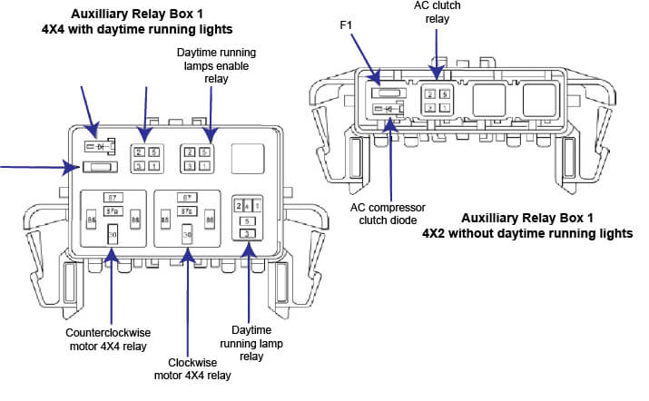
2006 Ford F150 Aux Relay Box Relay Diagram
Posted on by Rick Muscoplat