
2007 Fusion Fuse Diagram: Exploring the Fuse Boxes
2007 Fusion Fuse Diagram: Find the correct fuse for the circuit you’re working on
2007 Fusion Fuse Diagrams for Battery Junction Box and Smart Junction Box. The diagrams shown here also apply to: the 2007 Lincoln Zephyr and the 2007 Mercury Milan
To learn more about automotive fuses, see this article
To learn how to check a fuse visually or without removing it, see this article
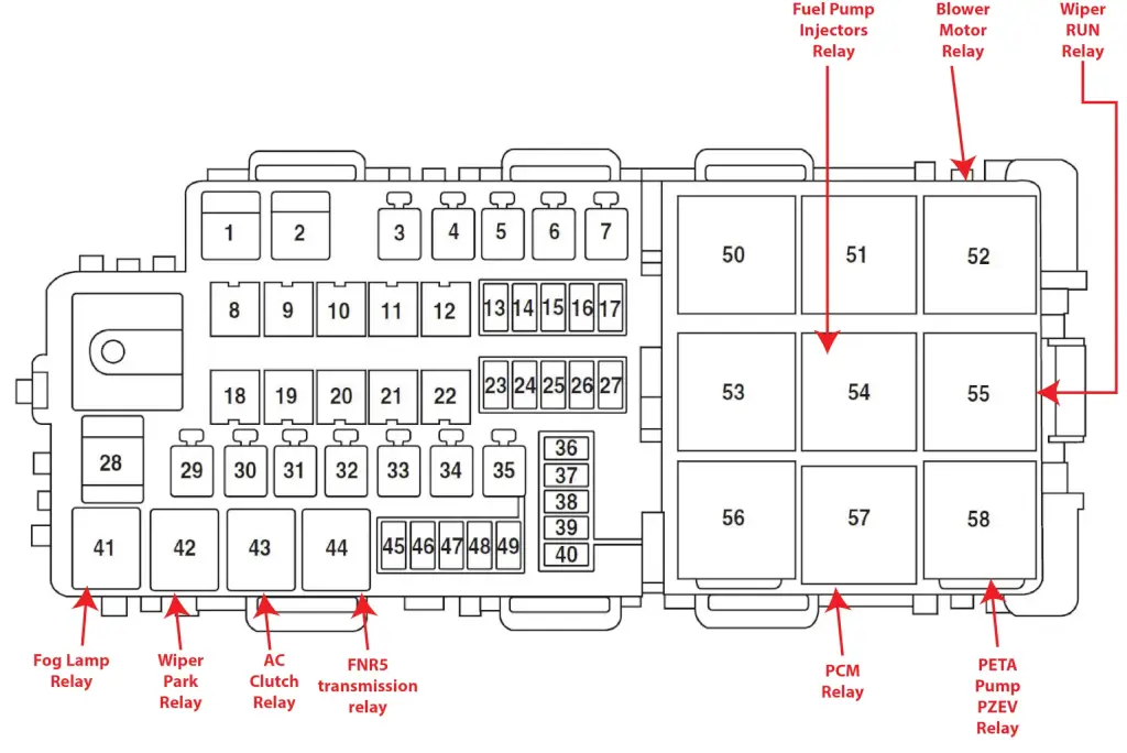
2007 Fusion Fuse Diagrams for Battery Junction Box
The battery junction box/power distribution box is located in the engine compartment. The power distribution box contains high-current fuses that protect your vehicle’s main electrical systems from overloads.
How to find your fuse and the devices served by that fuse
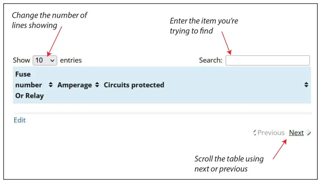
There are 62 fuse/relay slots in the Battery Junction Box. The chart shows only 10 to speed up load time. Here’s how to find the fuse and circuit you want.
1) Change the number of entries showing (in the Show Entries Box) to 100 and scroll the list.
2) Enter the name of the component you’re searching for in the Search box.
3) Use the Next/Previous buttons at the bottom of the table
| Fuse number | Amperage | Circuits protected |
|---|---|---|
| F1 | 60 | Smart Junction Box power feed (fuses 12, 13, 14, 15, 16, 17, 18, C/B) |
| F2 | 60 | Smart Junction Box power feed (fuses 1, 2, 4, 10, 11) |
| F3 | 40 | Powertrain power, PCM relay coil |
| F4 | 40 | Blower motor |
| F5 | — | Not used |
| F6 | 40 | Rear window defroster, Heated mirrors |
| F7 | 40 | PETA Pump (PZEV) power feed |
| F8 | 40 | ABS pump |
| F9 | 20 | Wipers |
| F10 | 30 | ABS Valves |
| F11 | 20 | Heated seats |
| F12 | — | Not used |
| F13 | — | Not used |
| F14 | 15 | Ignition switch |
| F15 | — | Not used |
| F16 | 15 | Transmission |
| F17 | 10 | Alternator sense |
| F18 | — | Not used |
| F19 | 40 | Logic feed to Smart Junction Box (solid state devices) |
| F20 | — | Not used |
| F21 | — | Not used |
| F22 | 20 | Console power point |
| F23 | 10 | PCM KAM, FNR5 and canister vent solenoid |
| F24 | 15 | Fog lamps |
| F25 | 10 | A/C Compressor clutch |
| F26 | — | Not used |
| F27 | — | Not used |
| F28 | 60 | Engine cooling fan |
| F29 | — | Not used |
| F30 | 30 | Fuel pump/injectors relay |
| F31 | — | Not used |
| F32 | 30 | Driver power seat |
| F33 | 20 | Moon roof |
| F34 | — | Not used |
| F35 | — | Not used |
| F36 | 1A | PCM diode |
| F37 | — | Not used |
| F38 | — | Not used |
| F39 | — | Not used |
| F40 | — | Not used |
| F41 | Relay | Fog lamp relay |
| F42 | Relay | Wiper park relay |
| F43 | Relay | A/C clutch relay |
| F44 | Relay | FNR5 transmission relay |
| F45 | 5 | PETA Pump (PZEV) feedback |
| F46 | 15 | Injectors |
| F47 | 15 | PCM class B |
| F48 | 15 | Coil on plug |
| F49 | 15 | PCM class C |
| F50 | — | Not used |
| F51 | — | Not used |
| F52 | Full ISO Relay | Blower relay |
| F53 | — | Not used |
| F54 | Full ISO Relay | Fuel pump/injectors relay |
| F55 | Full ISO Relay | Wiper RUN relay |
| F56 | — | Not used |
| F57 | Full ISO Relay | PCM relay |
| F58 | High Current Relay | PETA Pump (PZEV) |
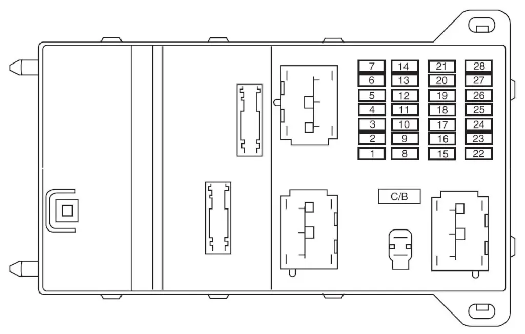
Fuse Diagram for Smart Junction Box
The cabin fuse panel is located below the dash on the driver’s side and to the left of the steering wheel by
the brake pedal. Remove the panel cover to access the fuses.
| Fuse number | Amperage | Circuits protected |
|---|---|---|
| F1 | 10 | Backup lamps (automatic transmission), Electrochromatic mirror |
| F2 | 20 | Horns |
| F3 | 15 | Battery saver: Interior lamps, Puddle lamps, Trunk lamp, Power windows |
| F4 | 15 | Parklamps, Side markers, License plate lamps |
| F5 | — | Not used |
| F6 | — | Not used |
| F7 | — | Not used |
| F8 | 30 | Rear window defroster |
| F9 | 10 | Heated mirrors |
| F10 | 30 | Starter coil, PCM |
| F11 | 15 | High beams |
| F12 | 7.5 | Delay accessories: Radio head units, Moon roof, Lock switch illumination, Electrochromatic mirrors, Ambient lighting |
| F13 | 7.5 | Cluster, Analog clock, Climate control head units |
| F14 | 15 | Washer pump |
| F15 | 15 | Cigar lighter |
| F16 | 15 | Door lock actuator, Decklid lock solenoid |
| F17 | 20 | Subwoofer |
| F18 | 20 | Radio head units, OBDII connector |
| F19 | — | Not used |
| F20 | 7.5 | Power mirrors |
| F21 | 7.5 | Stop lamps, CHMSL |
| F22 | 7.5 | Audio |
| F23 | 7.5 | Wiper relay coil, Cluster logic |
| F24 | 7.5 | OCS (Passenger’s seat), PAD indicator |
| F25 | 7.5 | RCM |
| F26 | 7.5 | PATS Transceiver, Brake shift interlock solenoid, Brake pedal switch, Automatic transmission relay coil, Reverse switch (back-up lamps for manual transmission) |
| F27 | 7.5 | Cluster, Climate control head units |
| F28 | 10 | ABS/Traction Control, Heated seats, Compass, Reverse sensing system |
| F29 | 30A Circuit Breaker | Moon roof power, Delayed accessory (SJB fuse 12, power window) |