
2006 F150 Fuse Box Diagram: Exploring the Fuse Boxes
2006 F150 Fuse Box Diagram: Find the correct fuse for the circuit you’re working on
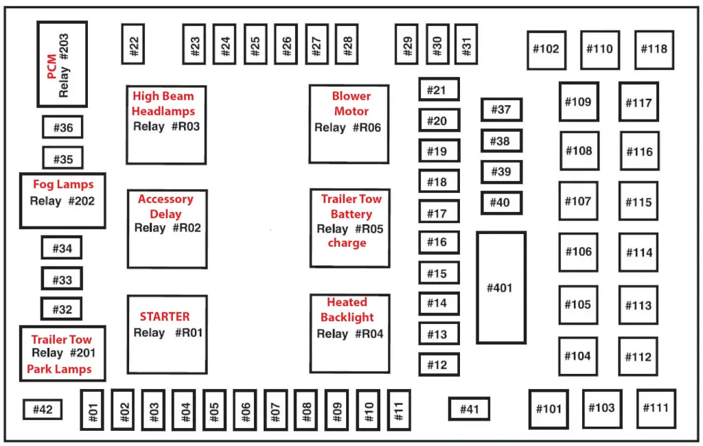
This article shows you the 2006 F150 Fuse Box Diagram for the Passenger Compartment Fuse Box, also called the Power Distribution Box or the Central Junction Box. In your 2006 Ford F150, the electrical system is designed with a primary fuse box and an auxiliary relay box. The Passenger Compartment Fuse Box, Power Distribution Box, or Central Junction Box, is located under the dashboard on the passenger side. To access this fuse box, you’ll need to crawl under the dash and locate the trim panel and fuse box cover concealed in the footwell area.
To access the fuses, remove the trim panel. Then, locate the pull tab on the fuse box cover and pull it off. To reinstall the cover, locate the top part on the fuse box and push the bottom part up until you hear it click.
To learn more about automotive fuses, see this article
To learn how to check a fuse visually or without removing it, see this article
Find the most commonly replaced fuses and bulbs here
The fuse box diagram and table below show all 71 fuses and all the relays. But most DIYers are looking for fuses and relays for the lights, power ports, and the blower motor. I’ve listed the most commonly checked/replaced fuses here to save time. I’ve also listed the most commonly replaced bulbs. A blown fuse or bulb are the two most common reasons for lighting issues.
• Backup Light: Fuse #14 10A, Bulb #3156
• Blower Motor: Fuse #116 30A and #13 10A
• Headlight Low Beam Passenger Side: Fuse #23 10A, Bulb #H13 (dual filament for high and low beams)
• Headlight Low Beam Driver’s Side: Fuse #25 10A, Bulb #H13 (dual filament for high and low beams)
• Headlights High Beam: Fuse #35 20A, Bulb #H13 (dual filament for high and low beams)
• Horn: Fuse #26 20A
• Parking lamps: Fuse #6 15A Mini Fuse, Front park turn bulb #3157A (amber)
• Power Ports: Rear: Fuse #37 20A, Instrument Panel: Fuse #39 20A, Cigar Lighter #41 20A, Overhead #18 10A
• Stop and Turn lights: Fuse #2 20A Mini Fuse, Bulb #4057 or #3057
2006 F150 Fuse Box Diagram for the passenger compartment fuse box/Central Junction Box/Power Distribution Box
To access the cabin fuse box, head to the right-hand side of the instrument panel, underneath the dashboard on the passenger side. First, you’ll need to remove the trim panel and fuse box cover. To do that, gently place a finger behind the “PULL” tab and your thumb just above it. Then, pull the cover off to reveal the fuses.
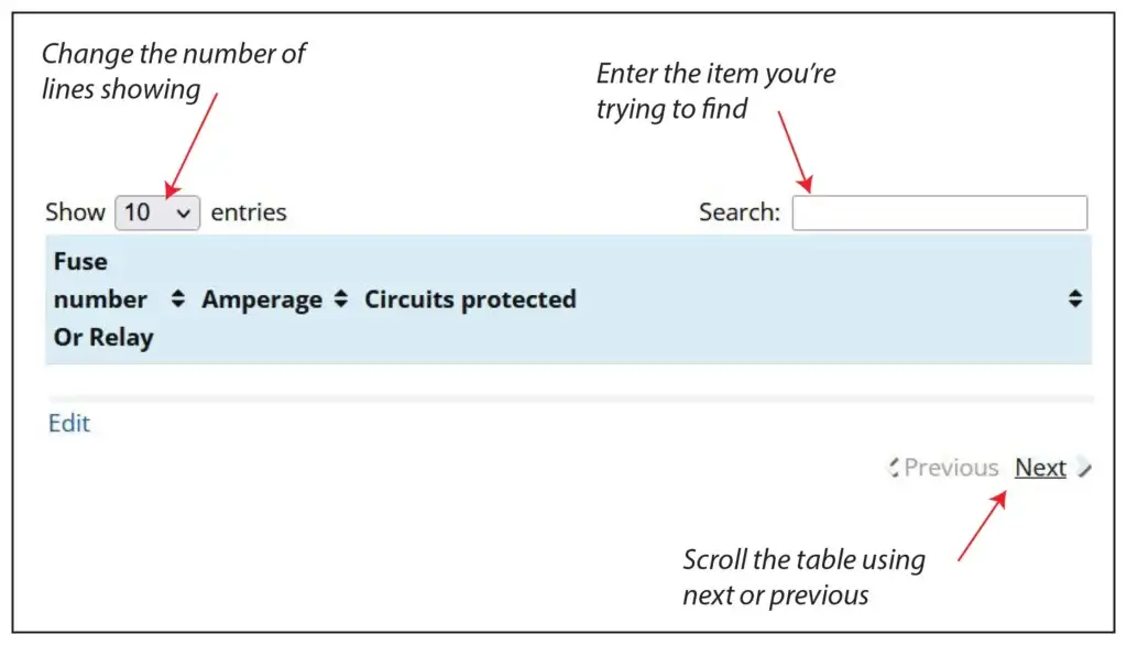
How to find your fuse and the devices served by that fuse
The Cabin Power Distribution Box has 71 slots for fuses and relays. The chart only displays 10 entries at a time. We do this to make it easier for you to find what you need. Here’s how you can find the fuse or circuit you’re looking for:
- Show more entries: To see more options, change the “Show Entries” box to display up to 100 items and then scroll through the list.
- Search for your component: Type the name of the component you’re looking for into the Search box to filter the list.
- Navigate through the list: Use the Next or Previous buttons at the bottom of the table to move through the list.
| Fuse number | Amperage | Circuits protected |
|---|---|---|
| F1 | 10 | Windshield wiper motor, Instrument cluster, Audio unit for XL/STX |
| F2 | 20 | Indicator flasher relay, Brake pedal position switch, stop/turn lamps |
| F3 | 7.5 | Exterior rear view mirror switch, Seat adjust switch, driver side front, Driver seat module |
| F4 | 10 | DVD player, Power folding mirror module |
| F5 | 7.5 | Powertrain Control Module (PCM), Autolamp/sunload sensor, Electronic Manual Temperature control (EMTC) module, Electronic Automatic Temperature Control (EATC) module |
| F6 | 15 | Main light switch, Body security module |
| F7 | 5 | Audio unit, Digital Transmission Range (DTR) sensor |
| F8 | 10 | Electronic Manual Temperature Control (EMTC) module, Electronic Automatic Temperature Control (EATC) |
| F9 | 20 | Fuel pump relay, Fuel injectors, Intake manifold runner control (4.2L) |
| F10 | 20 | Trailer tow relay, parking lamp, Trailer tow relay, reversing lamp, R201 |
| F11 | 10 | A/C clutch relay, Integrated wheel ends solenoid |
| F12 | 5 | PCM power relay |
| F13 | 10 | Electronic Manual Temperature Control (EMTC) module, Electronic Automatic Temperature Control (EATC) module, Indicator flasher relay |
| F14 | 10 | Digital Transmission Range (DTR) sensor, Daytime Running Lamps (DRL) relay, Deactivator switch, A/C high pressure switch, Heated Positive Crankcase Ventilation (PCV) valve, ABS control module, Reversing lamps switch, Auxiliary relay box 1 |
| F15 | 5 | Floor shifter, Overdrive cancel switch, Instrument cluster, Traction control switch |
| F16 | 10 | Brake pedal position switch/ Brake-shift interlock solenoid |
| F17 | 15 | Fog lamp relay |
| F18 | 10 | Parking Aid Module (PAM), Electronic compass, Electrochromatic inside mirror unit, Heated seat module, driver side front, Heated seat module, passenger side front, Body security module, Auxiliary power point |
| F19 | 10 | Passenger Air Bag Deactivation (PAD) switch, Seat weight sensor module, Restraints control module |
| F20 | 10 | Auxiliary power point |
| F21 | 15 | Instrument cluster |
| F22 | 10 | Audio unit, Roof opening panel switch, Door lock switch, passenger side, Door lock switch, driver side |
| F23 | 10 | Headlamp, right |
| F24 | 15 | Battery saver relay |
| F25 | 10 | Headlamp, left |
| F26 | 20 | Horn relay |
| F27 | 5 | Passenger Air bag Deactivation (PAD) indicator, Instrument cluster |
| F28 | 5 | SecuriLock transceiver (PATS), PCM IGN monitor |
| F29 | 15 | PCM 4x4 power |
| F30 | 15 | PCM 4x4 power |
| F31 | 20 | Radio power |
| F32 | 15 | EVAP canister purge valve, A/C clutch relay, Charge Motion Control Valve (CMCV), Valve cover assembly, left, Heated Oxygen Sensor (HO2S)#11, Heated Oxygen Sensor (HO2S) #21, Manifold Absolute Pressure/Intake Air Temperature (MAP/IAT) sensor, Positive crankcase ventilation heater, EGR system module, Variable Camshaft Timing (VCT) valve 1, Variable camshaft Timing (VCT) valve 2, Intake manifold Tuning Valve (IMTV), Camshaft position sensor |
| F33 | 15 | PCM power |
| F34 | 20 | Fog lamp relay, Daytime Running Lamps (DRL) relay, Headlamp, right, Headlamp, left, Instrument cluster, Fog lamps, Main light switch |
| F35 | 10 | Trailer tow connector, Park/stop/turn lamp, right rear |
| F36 | 20 | Power point, console 1, Power point, console 2 |
| F37 | 20 | Shift solenoid, CMS #12 and #22, Ignition coils |
| F38 | 25 | Subwoofer |
| F39 | 20 | Power point, instrument panel |
| F40 | 20 | Daytime Running Lamps (DRL) enable relay, Body security module, Main light switch, Multifunction switch |
| F41 | 20 | Data Link Connector (DLC), Cigar lighter, front |
| F42 | 10 | Trailer tow connector, Park/stop/turn lamp, left rear, Multifunction switch |
| F101 | 30 | Starter solenoid |
| F102 | 20 | Ignition switch |
| F103 | 20 | ABS control module |
| F104 | — | Not used |
| F105 | 30 | Trailer electronic brake control module |
| F106 | 30 | Trailer tow relay, battery charge |
| F107 | 30 | Power door locks Body security module (BSM) |
| F108 | 30 | Seat adjust switch, passenger side front |
| F109 | 30 | Adjustable pedal switch, Seat adjust switch, driver side front, Driver seat module |
| F110 | — | Not used |
| F111 | 30 | Clockwise (CW) motor 4x4 relay, Counterclockwise (CCW) motor 4x4 relay |
| F112 | 40 | ABS control module |
| F113 | 30 | Windshield wiper motor and washer pump |
| F114 | 40 | Heated backlite, Heated mirror power |
| F115 | — | Not used |
| F116 | 30 | Front blower motor relay |
| F117 | — | Not used |
| F118 | 30 | Heated seat module, driver side front, Heated seat module, passenger side front |
| F401 | 30 Circuit Breaker | Power sliding window switch, rear, Roof opening panel module, Master window adjust switch, Window adjust switch, passenger side |
| R01 | Full ISO relay | Starter solenoid |
| R02 | Full ISO relay | Accessory delay |
| R03 | Full ISO relay | Hi-beam headlamps |
| R04 | Full ISO relay | Heated backlite |
| R05 | Full ISO relay | Trailer tow battery charge |
| R06 | Full ISO relay | Blower motor |
| R201 | Half ISO relay | Trailer tow park lamps |
| R202 | Half ISO relay | Fog lamps |
| R203 | Half ISO relay | PCM |
2006 F150 Auxiliary Relay Box
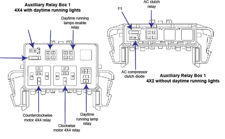
2006 Ford F150 Aux Relay Box Relay Diagram
Tips to diagnose electrical issues on your 2006 F150
If your power windows don’t work
• The power windows don’t use fuses. They get power from a 30A circuit breaker #401 in the fuse box diagram above.
If your blower motor doesn’t work
The blower motor gets its power from the blower motor relay #R06 in the fuse box diagram above. Power comes into the motor on the brown/yellow wire. It seeks ground through the brown/white wire, which runs to the fan speed switch and then to ground #203, located in the passenger footwell.
If the circuit you’re working on contains a relay
• A simple way to test a relay is to swap in a similarly shaped relay and see if the component works.
• If that doesn’t work, remove the relay and test for power to the relay control coil and contacts using a multimeter. For more information on relay testing, see this article.
Difference between 2006 and 2024 Ford F-150 Fuse Boxes
2006 Ford F-150:
• Fuse Types: Utilizes traditional blade-style fuses.
• Dual Fuse Boxes: Features two fuse boxes—one under the hood and another inside the cabin in the driver’s footwell. The underhood box manages engine-related fuses, while the cabin box handles accessory systems and smaller electrical circuits.
• Older Electrical Layout: Electrical architecture is simpler compared to newer models, which can impact maintenance and troubleshooting.
2024 Ford F-150:
• Advanced Fuse Technology: Uses the latest fuses and relays for precise protection of circuits and components.
• Single, Streamlined Fuse Box: Likely features a more centralized and efficient fuse box placement for ease of access and maintenance.
• Smart Electrical Systems: Integrates modern electrical systems, including electric and hybrid technologies, advanced driver-assistance systems, and sophisticated infotainment features. This requires a complex and carefully planned electrical design.
• Upgraded Layout: Designed to accommodate modern technology and safety features, resulting in a more sophisticated and optimized electrical architecture.
The 2024 model showcases substantial advancements in fuse box technology and electrical design compared to the 2006 model, driven by the evolution of vehicle technology and safety standards.
Posted on by Rick Muscoplat