
2012 Malibu Fuse Box Diagram: Exploring the Fuse Boxes
2012 Malibu Fuse Box Diagram: Find the correct fuse for the circuit
The 2012 Malibu has three fuse boxes; an underhood fuse box, an instrument panel fuse box, also called the Body Control Module (BCM), and a rear compartment fuse box . The engine compartment fuse box is located on the driver’s side of the engine compartment and covered with a lid to protect the fuses against water splash. For this reason, always reinstall the cover after working on the fuse box. The instrument panel fuse box is located under the dash on the passenger side of the vehicle. You’ll find the rear compartment fuse box in the trunk on the driver’s side of the vehicle. To access this fuse box, remove the panel cover. This post shows the 2012 Malibu fuse box diagram for both boxes, BCM and the circuits covered for each fuse
To learn more about automotive fuses, see this article
To learn how to check a fuse visually or without removing it, see this article
Find the most commonly replaced fuses here
The fuse box diagram and table below show all 62 fuses and all the relays. But most DIYers are looking for fuses and relays for the lights, power ports, and the blower motor. I’ve listed the most commonly checked/replaced fuses here to save time. I’ve also listed the most commonly replaced bulbs. A blown fuse or bulb are the two most common reasons for lighting issues.
Instrument panel fuse box/Body Control Module = BCM, Underhood fuse box = UFB, Rear Compartment Fuse Box = RCFB
• Backup Light: Fuse #17 RCFB
• Blower Motor: Fuse #79 20A BCM
• Headlight Low Beam Passenger Side: Fuse #9 10A UFB
• Headlight Low Beam Driver’s Side: Fuse #7 10A UFB
• Headlight High Beam Passenger Side: Fuse #12 10A UFB
• Headlight High Beam Driver’s Side: Fuse #11 10A UFB
• Horn: Fuse #8 15A UFB
• Stop/Turn/Brake: Fuse #47 10A UFB
• Parking lamps: Fuse #6 10A RCFB
Power Windows: Driver’s Door Module Fuse #25 30A PCFB, Passenger Door Module Fuse #26 30A PCFB. Rear Windows 30A circuit breaker PCFB and Fuse#23 10A PCFB
A note about fuses, battery power and keep alive memory
If you disconnect the battery or remove the PCM fuses from the fuse box, the PCM will lose its adaptive memory and baseline throttle body position. You can avoid this by providing backup power using a jumper pack and an inexpensive OBDII cable. See this article for more information on providing backup power to prevent the loss of adaptive memory. Or, you can perform a throttle body relearn procedure and then drive the vehicle so it can relearn the new adaptive memory settings. See this article for instructions on how to perform a 2012 Malibu throttle body relearn procedure.
2012 Malibu Fuse Box Diagram for the underhood fuse box
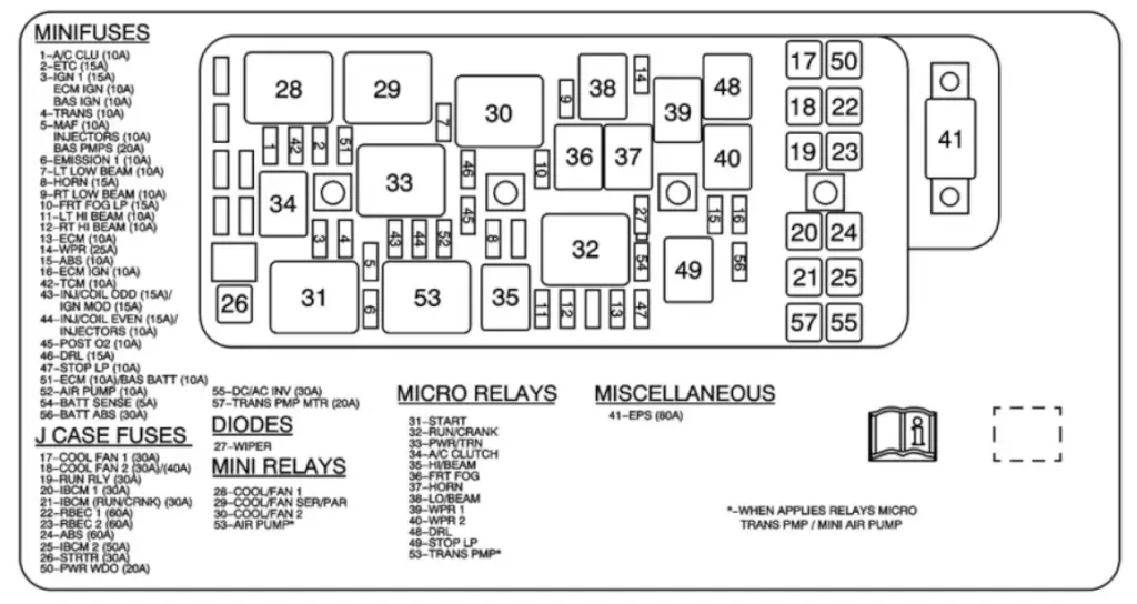
2012 Mailbu fuse box diagram underhood fuse box
| Fuse Name | Amperage | Circuits Protected |
|---|---|---|
| F1 | 10 | A/C CLUTCH Relay |
| F2 ETC | 15 | Electronic Throttle Control |
| F3 IGN 1 | 15 | Not Used |
| F4 TRANS | 10 | Transmission Control Module Ignition 1 |
| F5 MAF | 10 | Mass Airflow Sensor (MAF)/Intake Air Temperature (IAT) |
| F6 EMISSION | 10 | Evaporative Emission (EVAP) Canister Purge Solenoid Valve, Heated Oxygen (HO2S) Sensors, Mass Air Flow (MAF)/Intake Air Temperature (IAT) Sensor |
| F7 LT LOW BEAM | 10 | Left Low Beam |
| F8 HORN | 15 | Horn Relay, Horn Assembly |
| F9 RT LOW BEAM | 10 | Right Low Beam |
| F10 FRT FOG LP | 15 | Fog Lamp Relay |
| F11 LT HI BEAM | 10 | Left High Beam |
| F12 RT HI BEAM | 10 | Right High Beam |
| battF13 ECM | 10 | Engine Control Module (ECM), Telematic Vehicle Localization and Immobilization Control Module |
| F14 WPR | 25 | Wiper 1 Relay, Wiper 2 Relay, Windshield Wiper Motor Assembly |
| F15 ABS | 10 | Electronic Brake Control Module (EBCM |
| F16 ECM IGN | 10 | Engine Control Module (ECM), Telematic Vehicle Localization and Immobilization Control Module |
| F17 COOL FAN 1 | 30 | COOL/FAN 1 Relay |
| F18 COOL FAN 2 | 30 | COOL/FAN 2 Relay |
| F19 RUN RLY | 30 | Blower Motor Control Module, HVAC BLOWER HIGH Relay, and RUN Relay |
| F20 IBCM 1 | 30 | Body Control Module (BCM), AIRBAG (BATT) Fuse, CLUSTER/THEFT Fuse, HVAC CTRL (BATT) Fuse, IGN SENSOR Fuse, and RADIO Fuse |
| F21 IBCM (RUN/CRNK) | 30 | AIR BAG (IGN) Fuse, EPS Fuse, and RUN/CRANK Fuse |
| F22 RBEC 1 | 60 | AUDIO AMP Fuse, BCK/UP LAMPS Fuse, CIG/AUX Fuse, HTD SEAT Fuse, RKE/XM Fuse, S/ROOF Fuse, and R/WDO DEFOG Relay |
| F23 RBEC 2 | 60 | DRV SEAT Fuse, EMISSION 2 Fuse, FUEL PUMP Fuse, PRK LAMPS Fuse, PSG SEAT Fuse, and TRUNK Fuse |
| F24 ABS | 60 | Electronic Brake Control Module (EBCM) |
| F25 IBCM 2 | 50 | Body Control Module, DOOR LOCK Fuse, INTERIOR LIGHTS Fuse, ONSTAR Fuse , POWER MIRRORS Fuse, and ACCESSORY Relay |
| F26 STRTR | 30 | START Relay |
| F27 WIPER Diode | Diode | Wiper 1 Relay, Wiper 2 Relay |
| F28 COOL/FAN 1 | Relay | Engine Cooling Fan – Left |
| F29 COOL/FAN SER/PAR | Relay | Engine Cooling Fan – Left, Engine Cooling Fan – Right |
| F30 COOL/FAN 2 | Relay | Engine Cooling Fan – Right |
| F31 START | Relay | Starter Motor |
| F32 RUN/CRANK | Relay | ABS Fuse, IBCM (RUN/CRANK) Fuse, ECM IGN Fuse, MAF Fuse, ECM IGN Fuse, TRANS Fuse |
| F33 PWR/TRN | Relay | Emission 1 Fuse, ETC Fuse, INJ COIL ODD Fuse, IGN MOD Fuse, INJ COIL EVEN Fuse, INJECTORS Fuse, POST 02 Fuse, A/C CLUTCH Relay, AIR PUMP Relay |
| F34 A/C CLUTCH | Relay | A/C Compressor Clutch |
| F35 HI/BEAM | Relay | LT HIGH BEAM Fuse, RT HIGH BEAM Fuse |
| F36 FRT FOG | Relay | Fog Lamp – Left Front, Fog Lamp – Right Front |
| F37 HORN | Relay | Horn Assembly |
| F38 LO/BEAM | Relay | LT LOW BEAM Fuse, RT LOW BEAM Fuse |
| F39 WPR 1 | Relay | Wiper 2 Relay |
| F40 WPR 2 | Relay | Windshield Wiper Motor |
| F41 EPS | 80 | Power Steering Control Module |
| F42 TCM | 10 | Not Used |
| F43 INJ/COIL ODD | 15 | Fuel injectors ODD (LY7), Ignition Coil/Modules (ICM) IGN MOD Fuse 15A Ignition Coils |
| F44 INJ/COIL EVEN | 15 | Fuel Injectors EVEN, Ignition Coil Modules EVEN INJECTORS Fuse 10A Fuel Injector |
| F45 POST O2 | 10 | Heated Oxygen Sensor (HO2S) Bank 1 Sensor 2, Heated Oxygen Sensor (HO2S) Bank 2 Sensor 2) |
| F46 DRL | 15 | DRL Relay |
| F47 STOP LP | 10 | STOP Lamp Relay |
| F48 DRL Relay | Relay | Daytime Running Lamps |
| F49 STOP LP Relay | Relay | Center High Mounted Stop Lamp (CHMSL) and Tail/Stop Lamps |
| F50 PWR WDO | 20 | Window Motor – Driver, Window Motor – Passenger |
| F51 ECM | 10 | Not Used |
| F52 AIR PUMP | 10 | AIR PUMP Relay |
| F53 TRANS PMP | Relay | Not Used |
| F54 BATT SENSE | 5 | Body Control Module (BCM) |
| F55 DC/AC INV | 30 | DC/AC INVERTER |
| F56 BATT ABS | 30 | Electronic Brake Control Module (EBCM) |
| F57 TRANS PMP MTR | 20 | Not Used |
2012 Malibu Fuse Box Diagram for the Body Control Module
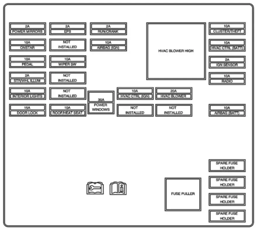
2012 Malibu fuse box diagram body control module
| Fuse Number | Amperage | Circuits Protected |
|---|---|---|
| ACCESSORY | Relay | POWER WINDOWS Fuse, ROOF/HEAT SEAT Fuse, WIPER SW Fuse |
| AIRBAG (BATT) | 10 | Inflatable Restraint Sensing and Diagnostic Module (SDM) |
| AIRBAG (IGN) | 10 | Inflatable Restraint Sensing and Diagnostic Module (SDM) |
| CLUSTER/THEFT | 10 | Instrument Panel Cluster (IPC) and Theft Deterrent Control Module |
| DOOR LOCK | 15 | Body Control Module (BCM) Logic |
| EPS | 2 | Power Steering Control Module (without NVH) |
| HVAC BLOWER | 20 | HVAC Control Module |
| HVAC BLOWER HIGH | Relay | Blower Motor |
| HVAC CTRL (BATT) | 10 | Data Link Connector (DLC) and HVAC Control Module |
| HVAC CTRL (IGN) | 10 | HVAC Control Module |
| IGN SENSOR | 2 | Ignition Switch |
| INTERIOR LIGHTS | 10 | Body Control Module (BCM) Logic |
| ONSTAR | 10 | Vehicle Communication Interface Module (VCIM) |
| PEDAL | 10 | Not Used |
| POWER MIRRORS | 2 | Outside Rearview Mirror Switch |
| POWER WINDOWS | 30 | Window Switch – Driver and Window Switch – Passenger |
| RADIO | 10 | Radio |
| ROOF/HEAT SEAT | 10 | Heated Seat Control Module – Driver), Heated Seat Control Module – Passenger, Heated Seat Switch – Driver, Heated Seat Switch – Passenger, Inside Rearview Mirror, and Sunroof Control Module |
| RUN | Relay | HVAC BLOWER Fuse, HVAC CTRL IGN Fuse |
| RUN/CRANK | 2 | A/T Shift Lock Control Assembly, Cruise Control On/Off Switch, Inflatable Restraint I/P Module Indicator |
| STR/WHL ILLUM | 2 | Steering Wheel Controls |
| WIPER SW | 10 | Windshield Wiper/Washer Switch |
Relays listed below are non-serviceable Printed Circuit Board (PCB) relays and are internal to the block.
DOOR LOCK PCB Relay — Door Lock Actuator – Driver, Door Lock Actuator – Passenger, Door Lock Actuator – LR, Door Lock Actuator – RR
DOOR UNLOCK PCB Relay — Door Lock Actuator – Driver, Door Lock Actuator – Passenger and Door Lock Actuator – LR
DR DOOR UNLOCK PCB Relay — Door Lock Actuator – Driver
INTERIOR LIGHTS PCB Relay — Courtesy Lamp, Dome/Reading Lamp, Rear Compartment Courtesy Lamp, Vanity Mirror Lamp – Left and Vanity Mirror Lamp – Right
2012 Malibu Fuse Box Diagram for rear fuse box
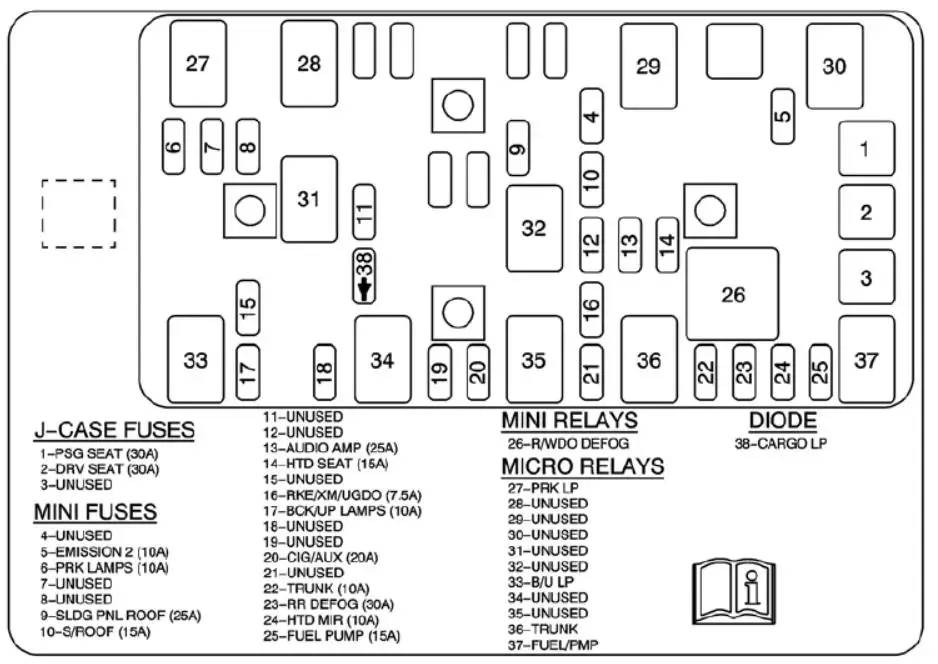
2012 Malibu fuse box diagram rear fuse box
| Fuse Number | Amperage | Circuits Protected |
|---|---|---|
| F1 PSG SEAT | 30 | Seat Adjuster Switch – Passenger |
| F2 DRV SEAT | 30 | Seat Adjuster Switch – Driver |
| F3 | — | Not Used |
| F4 | — | Not Used |
| F5 EMISSION 2 | 10 | Evaporative Emission (EVAP) Canister Vent Solenoid Valve |
| F6 PRK LAMPS | 10 | PARK Lamps Relay |
| F7 | — | Not Used |
| F8 | — | Not Used |
| F9 SLDG PNL ROOF | 25 | Sunroof Control Module, Sunroof Shade Module |
| F10 S/ROOF | 15 | Sunroof Control Module |
| F11 | — | Not Used |
| F12 | — | Not Used |
| F13 AUDIO AMP | 25 | Audio Amplifier |
| F14 HTD SEAT | 15 | Heated Seat Control Module – Driver and Heated Seat Control Module – Passenger |
| F15 | — | Not Used |
| F16 RKE/XM/UGDO | 7.5 | Digital Radio Receiver, Garage Door Opener Transmitter, and Remote Control Door Lock Receiver (RCDLR) |
| F17 BCK/UP LAMPS | 10 | BU/LP Relay |
| F18 | — | Not Used |
| F19 | — | Not Used |
| F20 CIG/AUX | 20 | Auxiliary Power Outlet – Console), Auxiliary Power Outlet – Front, and Cigar Lighter |
| F21 | — | Not Used |
| F22 TRUNK | 10 | TRUNK Relay |
| F23 RR DEFOG | 30 | Rear Window Defogger Grid |
| F24 HTD MIR | 10 | Outside Rearview Mirror – Driver, Outside Rearview Mirror – Passenger |
| F25 FUEL PUMP | 15 | FUEL/PMP Relay |
| F26 | Relay | Rear Window Defogger |
| F27 | Relay | Park Lamps |
| F28 | Relay | Not Used |
| F29 | Relay | Not Used |
| F30 | Relay | Not Used |
| F31 | Relay | Not Used |
| F32 | Relay | Not Used |
| F33 | Relay | Back-up Lamps |
| F34 | Relay | Not Used |
| F35 | Relay | Not Used |
| F36 | Relay | Trunk Release |
| F37 | Relay | Fuel Pump |
| F38 | Diode | Cargo Lamp |