
2013 Elantra Fuse Diagram
2013 Hyundai Elantra Fuse Diagram
2013 Elantra Fuse Diagram
2013 Elantra Fuse Diagram for Smart Junction box
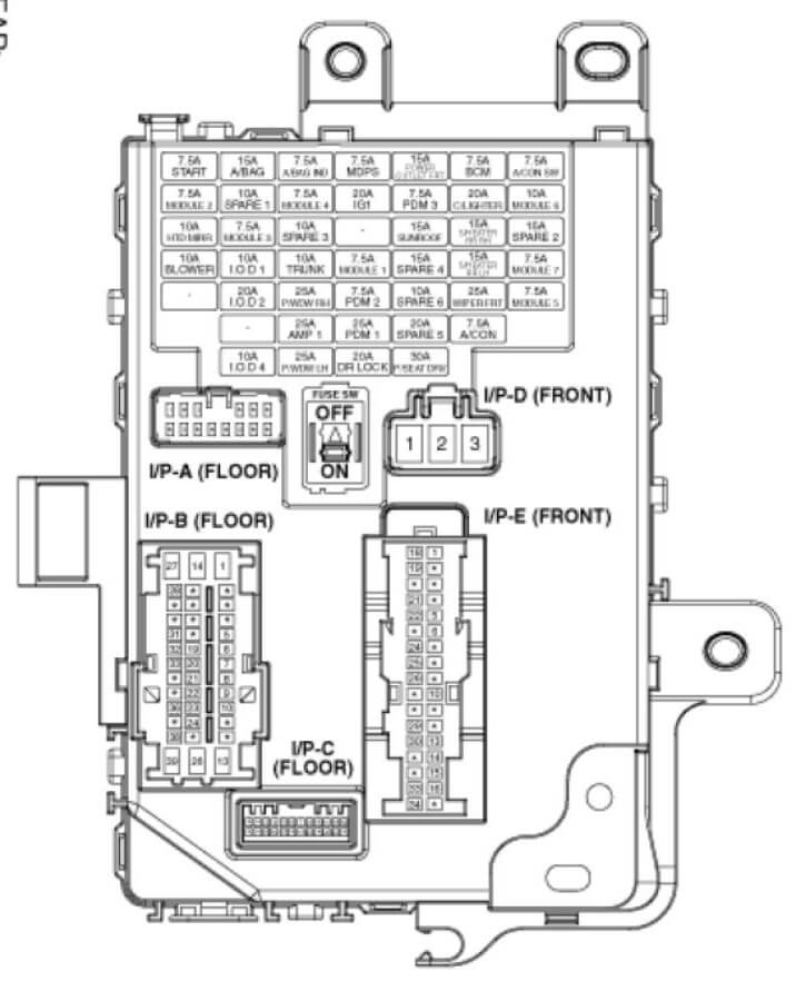
START 7.54 W/O Smart Key :ICM Relay Box (Burglar Alarm Relay)
With Smart Key :M/T – Transaxle Range Switch. M/T – ECM, E/R Fuse & Relay Box (Start 1 Relay). Smart Key Control Module
A/BAG 15A SRS Control Module. Passenger Weight Classification Sensor
A/BAG IND 7.5A Instrument Cluster \
MDPS 7.5A MDPS Unit
POWER OUTLET FRT 15A Power Outlet
BCM 7.5A Smart Key Control Module, BCM
A/CON SW 7.5A A/C Control Module
MODULE 2 7.5A Electro Chromic Mirror, ESC Off Switch, ICM Relay Box (HAC Relay). DC-DC Converter (AMP)
SPARE 1 10A –
MODULE 4 7.5A A/C Control Module (Auto NC). ATM Lever Indicator, ECO Switch. ISG Off Switch, Oil Pump Inverter, DC-DC Converter (Audio)
IG1 20A E/R Fuse & Relay Box (Fuse – TCU 1. B/UP LP. ECU 3. ABS 3)
PDM 3 7.5A Smart Key Control Module
C/LIGHTER 20A Cigarette Lighter
MODULE 6 10A AMP. Power Outside Mirror Switch. Audio. A/V & Navigation Head Unit. Digital Clock. DC-DC Converter (Audio/AMP)
HTD MIRR 10A Driver/Passenger Power Outside Mirror. A/C Control Module
MODULE 3 7.5A Audio. Tire Pressure Monitoring Module. Digital Clock, BCM, Instrument Cluster, Driver/Passenger Seat Warmer Module
BRAKE SWITCH 10A Stop Lamp Switch, Smart Key Control Module
AMP 2 204 AMP. DC-DC Converter (AMP)
SUNROOF 15A Sunroof
SPARE 7 15A –
SPARE 2 15A –
BLOWER 10A Manual A/C -A/C Control Module. ECM/PCM. Blower Resistor
INTERIOR LAMP 10A Luggage Lamp LH/RH, Vanity Lamp LH/RH. Room Lamp. Overhead Console Lamp. Ignition Key III. & Door Warning Switch(W/0 Smart Key)
TRUNK 10A Trunk Relay
MODULE 1 7.5A Sport Mode Switch (A/T). Key Solenoid (W/O Smart Key)
SPARE 4 15A –
S/HEATER RR 15A Rear Seat Warmer Switch LH/RH
MODULE 7 7.5A Smart Key Control Module, BCM
CLUSTER 10A With ISG – Audio. A/V & Navigation Head Unit. DC-DC Converter (Audio). Instrument Cluster
MULTIMEDIA 1 20A Audio. A/V & Navigation Head Unit. DC-DC Converter (Audio)
P/WDW RH 25A P/WDW RH Relay
PDM 2 7.5A Smart Key Control Module. Start Stop Button Switch
SPARE 6 10A –
WIPER FRT 25.4 Multifunction Switch, Wiper Motor, E/R Fuse & Relay Box (Wiper Relay)
MODULE 5 7.5A Cluster Ionizer (Auto A/C). Sunroof
AMP 1 25A AMP. DC-DC Converter (AMP)
PDM 1 25A Smart Key Control Module
SPARE 5 20A –
A/CON 7.5A A/C Control Module, E/R Fuse & Relay Box (Blower Relay)
MEMORY 10A The Pressure Monitoring Module, BCM. Auto Light & Photo Sensor. Instrument Cluster. Data Link Connector, Smart Junction Box Upgrade Connector. Electro Chromic Mirror. A/C Control Module, Digital Clock
P/WDW LH 25A P/WDW LH Relay, Driver Safety Power Window Module
DR LOCK 20A Door Lock Relay. Door Unlock Relay, ICM Relay Box (Two Turn Relay)
P/SEAT DRV 30A Driver Seat Manual Switch
2013 Elantra ER Fuse Diagram for the Fuse and relay box
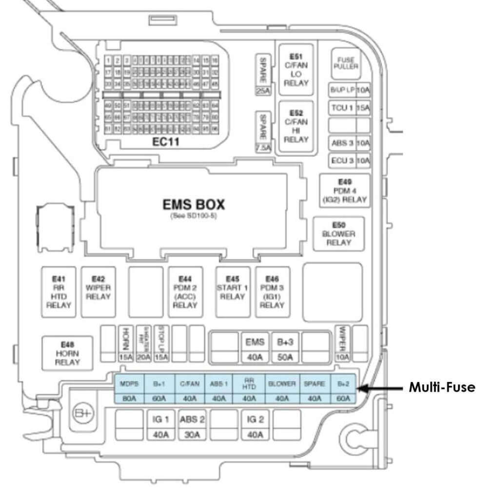
E41 RR HTD RELAY PLUG MICRO
E42 WIPER RELAY PLUG MICRO
E43 PLUG MICRO
E44 PDM 2 (ACC) RELAY PLUG MICRO
E45 START 1 RELAY PLUG MICRO
E46 PDM 3 (IG1) RELAY PLUG MICRO
E47 PLUG MINI
E48 HORN RELAY PLUG MICRO
E49 PDM 4 (IG2) RELAY PLUG MICRO
E50 BLOWER RELAY PLUG MICRO
E51 GIFAN LO RELAY PLUG MICRO
E52 C/FAN HI RELAY PLUG MICRO
MULTI-FUSE
MDPS 80A EPS Control Module
B+1 60A Smart Junction Box(ARISU 1 (4CH). IPS 1. FUSE • P/WDW LH, P/WDW RH, TRUNK, AMP 1) C/FAN 40A C/Fan Lo Relay, C/FAN Hi Relay C/FAN
ABS 1 40A ESC Module, Multipurpose Check Connector
RR HTD 40A RR HTD Relay
BLOWER 40A Blower Relay
SPARE 40A –
B+2 60A Smart Junction Box (Tum Signal Lamp Sound Relay, ARISU 2 (4CH), IPS (1CH), IPS (2CH), FUSE -ACZZ P/SEAT DRV, SUNROOF)
FUSES
BILJP LP 10A Electro Chromic Mirror, A/V & Navigation Head Unit, Rear Combination Lamp (In) LH/RH, MIT – Back-Up Lamp Switch, BCM, Instrument Cluster
TCU 1 15A MIT – Vehicle Speed Sensor, A/T – Transaxle Range Switch
ABS 3 10A ESC Module, Multipurpose Check Connector
ECU 3 10A Stop Lamp Switch, M/T – ECM, A/T – PCM
WIPER 10A Rain Sensor, M/T – ECM. A/T – PCM
8+3 50A Smart Junction Box(Leak Current Autocut Device, FUSE – MODULE 1, PDM 1, PDM 2, DR LOCK)
EMS 40A EMS Box(Engine Control Relay, FUSE – ECU 4, A/CON, F/PUMP)
STOP LP 15A Stop Lamp Switch, Smart Key Control Module
S/HEATER FFIT 20A Driver/Passenger Seat Warmer Module
HORN 15A Horn Relay
IG 2 40A W/0 Smart Key : Ignition Switch, Start 1 Relay, With Smart Key : PDM 4 (IG2) Relay, Start 1 Relay
ABS 2 30A ESC Module. Multipurpose Check Connector
IG 1 40A W/O Smart Key : Ignition Switch, With Smart Key : PDM 3 (IG 1) Relay, PDM 2 (ACC) Relay
2013 Elantra Fuse Diagram for the EMS box diagram
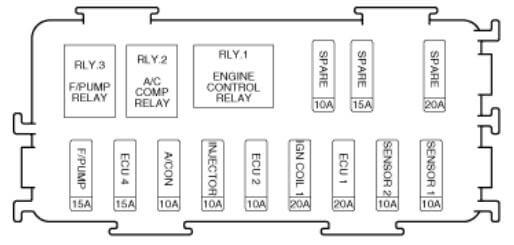
F/PUMP 15A F/PUMP Relay
ECU 4 15A PCM (A/T), ECM (M/T)
A/CON 10A A/C COMP Relay
INJECTOR 10A Injector #1 / #2 / #3 / #4, A/C COMP Relay, F/PUMP Relay
ECU 2 10A PCM (A/T), ECM (M/T)
IGN COIL 1 20A Ignition Coll #1 #2 #3 #4, Condenser
ECU 1 20A –
SENSOR 2 10A Immobilizer Module, Camshaft Position Sensor #1 / #2
Oil Control Valve #1 / #2, Purge Control Solenoid Valve, C/FAN LO Relay, C/FAN HI Relay
SPARE 10A –
SPARE 15A –
SPARE 20A –