
Honda dual mode alternator and charging systems explained
Learn how the Honda dual-mode alternator and charging systems work
Honda alternator and charging systems by generation. Honda has used several generations of charging systems in their vehicles. If you don’t know how the Honda alternator and charging systems work in your particular vehicle, it’s very easy to misdiagnose it and falsely conclude that the alternator has failed. Thousands of perfectly good Honda alternators are replaced each year. Let’s take a look at the different generations and how they work so you can avoid a misdiagnosis
NOTE on battery temperature and charging rates
Understanding temperature and charging voltages
Most lead-acid batteries need at least 14.2 charging volts to overcome the chemical resistance of the electrolyte. But that’s based on a battery temperature of 70°F. As electrolyte temperature drops and chemical activity slows, you need 14.5-volts or more or more to obtain the same amount of charging activity.
During summer months when battery temperatures are much higher and chemical activity increases, the battery charging voltage must be decreased to prevent boiling the water in the electrolyte. That’s why you may see charging voltages around 13.5-volts during full charging modes.
Knowing how temperature affects charging is part and parcel of understanding how charging systems work.
Early Honda alternator technology
The early Honda alternators used either an external or internal voltage regulator to control charging voltage and current. Both the mechanical external and solid-state internal voltage regulators include some type of temperature monitoring device used to control charging rates.
These early “stand-alone” systems never communicated with the vehicle ECM and they never monitored the vehicle’s current usage. These early systems weren’t very smart; their charging strategy was based only on the battery’s voltage or State-of-charge and ambient under-hood temperature.
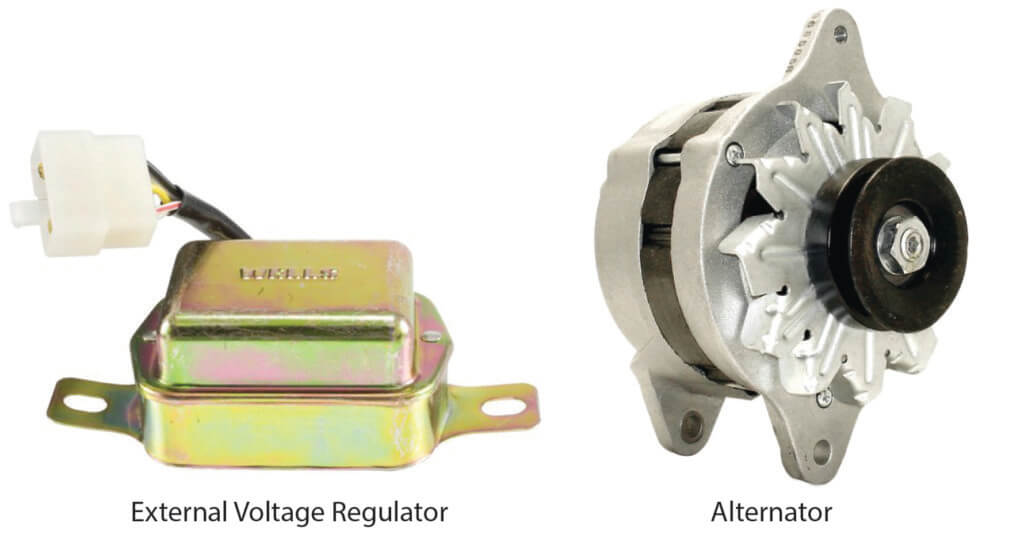
Honda alternator and voltage regulator
Drawbacks of voltage-only charging systems
Battery voltage is only one indication of battery condition. Battery voltage at a certain temperature tells you only one thing; the battery’s state-of-charge. It does not tell you the battery’s state-of-health. Let’s say, for example, that the battery has developed a shorted cell. If you test only voltage, the battery will appear as undercharged. No amount of charging will return a battery with a bad cell to a normal state of charge. That’s why current monitoring and “smart charging” was implemented.
Honda implements smart charging
As buyers purchased vehicles with more electrical features like heated seats, rear window defoggers, and better sound systems, the vehicle needed better electrical changing controls. Honda switched to alternators with internal voltage regulators that were controlled by the ECM via a local interconnect network (LIN). The system also included an Electric Load Detector (ELD). The ELD is far more than a voltage monitor. Think of it as an “amp-clamp” that measures vehicle amperage draw. First generation ELDs monitored battery voltage and amperage flowing to and from the battery fuse box or the positive or negative battery cable (the ELD placement varied by year and model).
In these early smart charging systems, the ECM is the “master” and the alternator is the “slave” following commands from the ECM. On engine startup, and once the engine reaches 500-RPM, the alternator begins status communication with the ECM. Alternator voltage must be above 10.0-volts and the communication must begin within 3-seconds or the ECM will set a trouble code.
The ECM set a charging voltage of 12.5-14.5-volts. The internal voltage regulator monitors the alternator output and reports it to the ECM. If the actual voltage didn’t match the commanded output, the ECM sets a P0562 (P1297) voltage too low or PP1549 for voltage too high. If the alternator doesn’t charge at all, the ECM sets a P056A for No Charging Malfunction. The voltage regulator also tracked internal temperature and reported it to the ECM if the internal temperature exceeded 320°. The ECM would then set a P16E4 trouble code.
Even though a typical lead-acid battery is considered fully charged at 12.6 volts, many of the early smart Honda systems were designed to see 12.4 volts, or 80% state-of-charge, as perfectly normal and the ECM would not command alternator charging. If you started this engine and measured voltage at the battery expecting to see voltage in the 13.0-13.5 range, you might misdiagnose this as a failed alternator.
That’s why testing while idling with no electrical loads on can lead to unnecessary alternator replacement. You must turn on electrical loads to test charging voltage. Even then, a voltage test, by itself, is not an accurate measure of the charging system’s performance. You must also check amperage.
Lessons from a smart charging system
The key to understanding a smart charging system is this:
When a charging system is monitoring amps in or out of the battery, the charging system’s MAIN function is to supply the electrical needs of the vehicle’s electrical components. Its MINOR function is to recharge the battery.
Honda Dual Mode Charging systems
Starting with many 2008 Honda and Acura vehicles use a dual-mode charging system. The system consists of an Electric Load Detector (ELD) to determine vehicle electrical load, an alternator with an internal voltage regulator, and communication with the ECM. The system is designed to produce just enough power to maintain electrical loads and recharge the battery. The dual-mode system is designed to increase fuel economy and reduce the load on the engine by up to 10%.
Honda alternator low output mode
During startup and periods of low electrical loads or after the battery has been recharged after startup, the ECM will set the charging voltage at a lower 12.4-12.9 volts. Honda maintains voltage at this low rate once the battery is fully charged in order to maintain battery charge. It’s important that you understand this low output mode as you can easily confuse this low voltage as a low charging problem when, in fact, it’s perfectly normal.
Low output mode is used when:
The electrical load below 15 Amps, although this varies with year, engine and model,
The vehicle speed between 10-45 mph or at idle while in drive,
The engine speed below 3,000 rpm,
The coolant temperature above 167°F
The A/C Switch is OFF
The intake air temperature above 68°F
Honda alternator high output mode
The ELD reports to the ECM and the ECM, along with various other sensors determines the charging voltage. For example, if the ECM detects an AC request and powers the AC compressor clutch, the ECM will set the charging rate at 14.4-14.9V. This is referred to as the high output mode
Outside of the above listed low output mode parameters, the ECM will place the charging system in the high output mode.
Honda dual-mode charging system components
Internal voltage regulator
Honda’s alternator internal voltage regulator performs three tasks
1) The Honda dual-mode alternator with integral voltage regulator controls power to the field coil (rotor). Based on commands from the ECM, the voltage regulator uses a pulse-width modulation technique to power the alternator’s field coil. In other words, the regulator pulses battery voltage and full current on and off to the field coil. If the voltage is on for .5 of a second, that’s referred to as a 50% duty cycle. When power is on for the full second, the alternator is at a 100% charging rate.
2) The internal regulator also communicates the field rotor status back to the ECM so it can determine the rate of charging.
3) The internal voltage regulator on some models controls the charge warning indicator lamp by toggling the ground side of the circuit on or off. However, on the latest Honda vehicles, the charge warning indicator lamp function is no longer part of the voltage regulator. When the alternator reports a problem to the ECM, the ECM sets a trouble code and communicates digitally with the gauge control module to light the BATTERY light on the instrument cluster.
The Electric Load Detector (ELD) Function
The ELD inside the fuse box or at the battery terminals. The ELD measures and reports the amount of electrical energy being used by the vehicle and reports this data to the ECM. The ECM provides a 5V reference to the ELD and the ELD pulls the reference voltage to ground as the electrical load increases.
For example, You should see 2-4 volts found at the ELD terminal when the vehicle is using little power and 1-2 volts when there is a high electrical load. \
Honda alternator five-wire wiring connections
The five terminal Honda alternators use these terminal functions
Ignition (IG) — The IG terminal is energized when you turn the IGN key to the RUN position. This power is used to power the voltage regulator.
Control (C) — The C terminal is used to communicate with the ECM to control the charging mode. The voltage regulator sends voltage to the ECM through this connection. Based on input from the ELD and various sensors, the ECM determines electrical load and charging mode. The ECM holds the voltage high to command the voltage regulator to operate in high output mode, or it pulls the voltage low to command low output mode (12.4-12.9V).
Field Reference (FR) — This terminal tells the ECM field (rotor) status. For example, if the field current is high, resistance to rotation will also be high. In that case, the ECM will increase engine idle speed. The ECM sends a 5-volt reference to the voltage regulator on the FR terminal. When the field is ON, the voltage regulator will pull this reference voltage down. When the field is OFF, the reference voltage will remain near 5 volts.
Battery (B) — This terminal/wire goes directly to the battery to recharge it. This is the output from the alternator. The ring terminal connects to a stud on the back of the alternator. All the other connections are in a plastic connector.
Lamp (L) — Honda has used two different methods of illuminating the charge warning indicator lamp. On some models, the L terminal provides ground to the charge warning indicator lamp, thus illuminating the bulb. At startup, before the field coil is energized, the terminal is ground and the warning light is lit. If the alternator is working as intended, the L terminal removes the ground and the light is out.
On newer model Honda vehicles, the ECM sends source voltage to the L circuit. In the event of a fault, the voltage regulator will pull the voltage to ground. The ECM senses the voltage drop and communicates with the gauge control module over the CAN bus to turn on the charge warning indicator light.
Diagnose a Honda No Charge Condition
On five-wire models, check for continuity between the B terminal and the battery positive terminal. With the IGN in the RUN position, check for battery voltage on the IG terminal.
Diagnose a Honda low charge condition on a dual charging mode Honda
If the BATTERY light is on:
1) Check for slipping alternator belt or idle speed too low before proceeding with any other tests
2) Check that no added electrical accessories have been connected directly to the battery cables. All vehicle power MUST be measured by the ELD or you will get faulty alternator operation
3) Check the C voltage in the alternator connector. If this connector/wire is shorted to ground, the alternator will stay in low output mode. This will result in dim headlights at stop lights or dim lights when turning on high load electrical accessories.
4) Check for short to ground or open on the L wire at the alternator connector.
If the BATTERY light is NOT on but the alternator is not charging:
1) Check for an open on the L terminal. An open on the L wire will never allow the charge warning light to come on, even during bulb test at key ON.
A P1298 (ELD circuit high voltage) can be caused by a faulty solder on the ELD. If this is the case, 5V will be found at the ELD signal terminal at the ECM. At first, technicians were required to replace the whole fuse box. However, technicians are now required to disassemble the fuse box and replace only the ELD. The same voltage will be found if there is a problem on the ground-side of the ELD.
P16BC (alternator FR terminal circuit/IGP circuit low voltage) will be set. If the ECM senses a charging voltage below 11V for at least 1 minute.
P0562 (charging system low voltage). In some cases, if all of the previously stated codes are set with other P-type codes such as P0102 (MAF sensor circuit low voltage) or P0141 (secondary HO2S [sensor 2] heater circuit malfunction), it might be caused by an open at terminal F5 (YEL) of connector F in the fuse box under the dash.
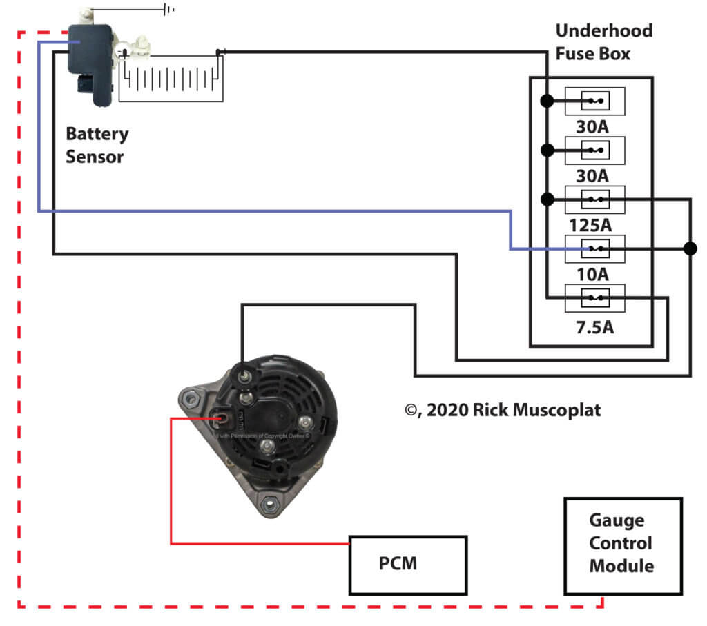
Honda two-wire alternator charging systems
This is the latest generation charging system. The alternator has two wires; the B wire goes directly to the underhood 125A fuse and then to the battery. The other wire goes to the ECM/PCM.
How the two-wire Honda charging system works
©, 2020 Rick Muscoplat
Posted on by Rick Muscoplat