
How the CAN Bus System Works in Modern Vehicles
Understanding the CAN Bus System and Can Bus Communication Problems
Quick Summary
Think of the Controller Area Network (CAN bus) as a digital highway that carries constant communication between every major module in your vehicle. When it works, everything is seamless. When it fails, you’ll see strange symptoms, no communication, or multiple fault codes that seem unrelated. The key takeaway is this: the CAN bus system is simple in design but unforgiving when something goes wrong. Once you understand how it communicates—and what different CAN bus errors actually mean—you can diagnose problems quickly and accurately instead of guessing.
How the CAN Bus System Works (And How I Diagnose CAN Bus Errors in the Real World)
I’ve spent a lot of time diagnosing electrical problems, and I can tell you firsthand—the CAN bus system is one of the most misunderstood parts of a modern vehicle. I’ve seen good technicians get completely turned around chasing the wrong problem simply because they didn’t understand what the network was actually telling them.
Once you get a handle on how the CAN bus system works, everything changes. Those confusing fault codes start to make sense, and instead of throwing parts at a problem, you start diagnosing with purpose.
How the CAN Bus System Works in Practice
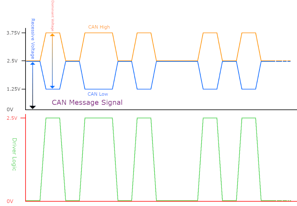
The CAN bus uses two wires to transmit data simultaneously. The two wires are referred to as CAN Hi (High) and CAN Lo (Low). CAN Hi usually measures from 2.5V to 3.75V, while CAN Lo measures from 2.5V to 1.25V. At rest, both lines read 2.5V. This is referred to as “Recessive,” the equivalent of a binary value of 1. When CAN Hi goes to 3.75V and CAN Lo goes to 1.25V, the signal is referred to as “Dominant,” the equivalent of a binary value of 0.
The wiring in a CAN bus system is very intentional, and it’s quite different from what you see in simpler single-wire communication setups. One of the biggest advantages—and something I’ve seen play out in real diagnostics—is how tolerant the network is of a failure at a single node.
If a module loses its connection because CAN High or CAN Low is cut going to that specific node, that module drops off the network—but the rest of the system keeps working. The other modules continue to communicate normally and don’t depend on that one connection to stay alive. That’s a huge advantage over single-wire systems, where one break can take everything down.
When I put a scope on a healthy CAN bus system, I’m looking for two clean, symmetrical waveforms. It’s one of those things that, once you’ve seen it a few times, becomes second nature. A clean waveform tells me the network is healthy before I even look at a scan tool.
When the CAN Bus System Fails
This is where things get interesting—and where a lot of people go wrong.
When a vehicle comes in with multiple warning lights or communication codes, the instinct is to blame the network itself. But in my experience, the CAN bus system is rarely the root cause. It’s usually reacting to a problem somewhere else. That’s why I always step back and ask: what kind of failure am I actually looking at?
CAN Bus Off: When a Module Drops Off the Network
One of the most serious faults you’ll encounter is a CAN bus off condition. I’ve seen this bring an entire vehicle to a standstill.
What’s happening here is pretty straightforward once you understand it. A control module keeps trying to send and receive data, but repeated failures cause it to hit an internal error limit. When that happens, it essentially shuts itself off from the network.
At that point, communication stops completely. Other modules begin reporting lost communication, and sometimes you can’t even talk to the affected module with your scan tool.
I’ve tracked this type of failure back to simple issues like:
• shorted wiring
• corroded connectors
• loose ground.
CAN Bus Timeout: When One Module Goes Silent
A CAN bus timeout is a little different. The network is still alive, but one module isn’t responding the way it should.
I’ve seen this when an engine control module stops receiving data from a transmission module, or when the ABS system drops out of communication. The rest of the network continues to function, but one piece is missing from the conversation.
When I see a timeout code, I don’t go hunting across the entire vehicle. I focus on the specific module mentioned in the code and work from there. More often than not, the issue is isolated—either a wiring problem or a power-and-ground issue at that module.
CAN Bus Message Errors: When the Data Is Wrong
This is the one that fools a lot of people.
A CAN bus message error doesn’t mean there’s no communication. It means the communication is bad. The data is getting through, but it’s incorrect.
I’ve run into situations where multiple modules were flagging communication errors, and it looked like a network problem at first glance. But when I dug deeper, the issue turned out to be something simple—a failed wheel speed sensor feeding bad data into the system.
Once that bad data entered the CAN bus system, every module that relied on it started throwing fault codes. Fix the sensor, and suddenly the “network problem” disappears. That’s why I always say: don’t blame the network until you verify the data.
How I Actually Diagnose a CAN Bus System
When I approach a can bus system problem, I don’t start with complex tools. I start with the basics.
The first thing I check is whether the module in question has power and ground. It sounds simple, but you’d be surprised how often a dead module is mistaken for a network failure.
Once I confirm power and ground, I move to the network itself. At the OBD-II connector, I check resistance across the CAN lines. A healthy system will show about 60 ohms, indicating the terminating resistors are intact.
From there, I check for shorts to ground or shorts between the wires. If something looks off, I start isolating sections of the network until I find the fault.
If I need more detail, I’ll bring out the oscilloscope. That’s where I can see exactly how the signal is behaving. A clean waveform tells me everything is working as it should. A distorted or missing signal points me directly to the problem.
What Causes Most CAN Bus System Failures
After years of doing this, I can tell you that most bus system failures come down to a handful of issues.
1) Wiring damage is at the top of the list, especially near connectors or areas exposed to moisture.
2) Corrosion is another big one—it doesn’t take much to disrupt a low-voltage communication network.
3) Poor grounds or aftermarket wiring that wasn’t installed properly.
And then there are the cases where the network is perfectly fine, but a sensor or module is feeding bad data into the system, causing everything else to react.
Final Thoughts: How to Think About the CAN Bus System
If you take nothing else away from this, remember this one idea. The CAN bus system is just a communication network. It doesn’t create problems—it reveals them.
When you see CAN bus errors, don’t panic and don’t assume the worst. Step back, understand what the network is telling you, and follow the data. Once you do that, even the most confusing electrical problems start to fall into place.
©, 2026 Rick Muscoplat
Posted on by Rick Muscoplat