
How to Test a Crankshaft Position Sensor Like a Pro
Step-by-Step Crankshaft Position Sensor Testing Methods
Quick Summary
Testing a crankshaft position sensor isn’t just about whether it’s producing a signal; it’s about whether it’s producing the right signal at the right strength and under the right conditions. The biggest takeaway is this: a crank sensor can pass basic tests and still fail in real-world operation. That’s why I always combine resistance checks, voltage tests, and—most importantly—signal analysis with a scope. If you understand how the sensor works and follow a structured diagnostic approach, you can pinpoint failures quickly and avoid unnecessary parts replacement.
Why Testing a Crankshaft Position Sensor Requires a Strategy
I’ve seen a lot of guys throw parts at a no-start or intermittent stall, assuming the crankshaft position sensor is bad. Sometimes they get lucky—but that’s not how I work. When I test a crankshaft position sensor, I’m thinking about three things:
• Is the sensor producing a signal?
• Is the signal strong enough?
• Is the signal accurate and consistent?
Because here’s the reality: these sensors rarely fail cleanly. They fail intermittently, they fail when hot, or they produce weak signals that confuse the PCM.
Understanding How the Sensor Generates a Signal
A crankshaft position sensor reads a reluctor wheel (trigger wheel) attached to the crankshaft. As the engine rotates:
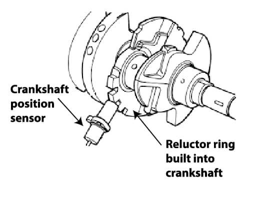
In many engines, the reluctor ring is built into the crankshaft. On others, it’s mounted under the harmonic balancer.
• Teeth pass the sensor
• A signal is generated
• A missing tooth tells the PCM engine position
That missing tooth is critical—it’s the reference point the computer uses to sync ignition and fuel timing. If that pattern is distorted, the engine can misfire, stall, or fail to start.
The Two Types of Crankshaft Position Sensors
Every time I test a crankshaft position sensor, I first identify which type I’m dealing with. That determines everything about how I test it. If you don’t know which type you’re working with, you’re already behind.
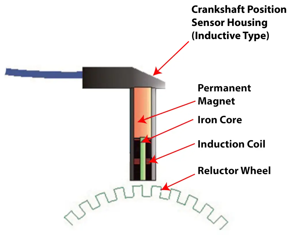
1. Passive Type: Magnetic (Inductive) Sensor — This is the older, more traditional design. It consists of a wire coil wrapped around a permanent magnet positioned near a toothed reluctor wheel (tone ring) attached to the crankshaft.
How it works:
As the crankshaft spins, each metal tooth on the reluctor wheel passes by the sensor tip. This interrupts and changes the magnetic field around the coil, inducing an alternating current (AC) voltage — no external power supply is needed for this design. The signal looks like a sine wave, and its frequency increases with engine RPM. One or more missing teeth on the reluctor wheel create a recognizable gap in the signal, telling the ECU the exact rotational reference point (TDC).
• Output: Analog AC sine wave
• Requires: No external power
• Weakness: Signal is weak at very low RPM (hard starting)
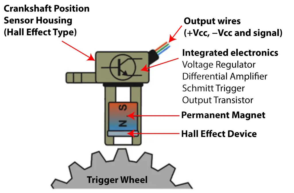
2. Active Type: Hall Effect Sensor — This is the modern, more precise design. It uses a semiconductor (Hall element) and requires an external power supply (typically 5–12V from the ECU).
How it works:
When a magnetic field passes perpendicularly through the Hall element (triggered by each tooth on the reluctor wheel), it causes a measurable shift in voltage across the semiconductor. Internal circuitry converts this into a clean on/off digital square-wave signal that is sent to the ECU. Some versions use a magnetic reluctor wheel; others use a magnet embedded in the wheel itself.
• Output: Digital square wave (0V / 5V)
• Requires: External power (2- or 3-wire connector)
• Strength: Accurate signal even at near-zero RPM; more reliable in general
How I Test a Passive Inductive Crankshaft Position Sensor
Resistance Test (Quick Check) — I start by measuring resistance across the two terminals. If it’s out of spec, the sensor is bad—no question. But here’s what most people don’t understand: If it’s in spec, that does NOT mean it’s good. I’ve seen plenty of sensors pass resistance tests and still fail under load.
AC Voltage Output Test — Next, I switch my meter to AC voltage and crank the engine. If I see AC voltage, I know the sensor is generating a signal. But I don’t stop there, because voltage alone doesn’t tell the whole story.
Lab Scope Analysis (Where the Truth Is) — This is where I separate guesswork from real diagnostics. With a scope, I can:
• See each tooth of the reluctor wheel
• Identify the missing tooth (sync point)
• Detect signal dropouts or glitches
A clean waveform tells me the sensor and reluctor are working together correctly. A distorted waveform tells me there’s a deeper issue—possibly mechanical damage or sensor spacing problems.
How I Test a Digital Hall Effect Crankshaft Position Sensor
Step 1: Verify Reference Voltage — I check for a 5V (or sometimes higher) reference from the ECM. If there’s no reference voltage or the wrong voltage, the problem isn’t the sensor—it’s the circuit or ECM.
Step 2: Check Ground Integrity — I verify a solid ground. Even a slight voltage drop here can distort the signal.
Step 3: Analyze the Signal Wire — Here’s where most DIY tests fall short. You might see voltage on a multimeter, but all multimeters average the reading. A multimeter can’t show what the signal is actually doing. To do that, you need a scope.
With a scope, I look for with a scope:
• A clean square wave
• Full switching between high and low voltage
• Consistent pattern with no dropouts
I’ve seen sensors produce a square wave that never drops low enough for the ECM to recognize it. The signal looks “okay” on paper—but the engine won’t run.
The Most Overlooked Problem: Signal Strength and Air Gap
This is something I see all the time, especially here in the Rust Belt. When I test a crankshaft position sensor, I always check the air gap between the sensor and the reluctor wheel. If the gap is too large:
• The signal becomes weak
• Voltage drops below PCM threshold
• The engine may crank but not start
Even rust buildup or improper installation can change that gap enough to cause failure. And the tricky part? You might still see a signal—but it’s not strong enough to be usable.
Don’t Forget the Reluctor Wheel
I never test a crank sensor in isolation. The reluctor wheel can:
• Crack
• Lose teeth
• Become magnetized
• Be installed incorrectly
Any of those issues will distort the signal. I’ve seen engines backfire and fail to start simply because the reluctor was damaged or misaligned.
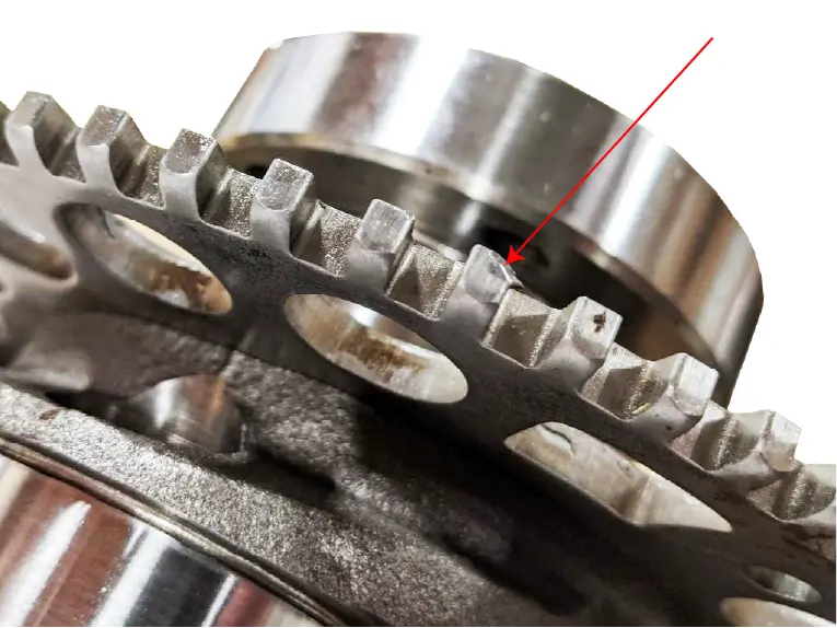
Damaged reluctor wheel
Final Thoughts From the Shop
When I test a crankshaft position sensor, I’m not looking for a quick yes-or-no answer. I’m building a complete picture of how the sensor, reluctor, and PCM interact.
If you take one thing from this, it’s this:
A crank sensor test isn’t complete until you’ve verified the signal quality—not just its existence.
That’s how you avoid misdiagnosis and fix the problem the first time.
Posted on by Rick Muscoplat