
Master the Basics: How to Use a Multimeter Like a Pro
Diagnosing Automotive Faults with a Multimeter: A Practical Guide
A multimeter is an invaluable tool for diagnosing automotive electrical problems. With the right knowledge, you can tackle many issues without a trip to the mechanic. Here’s how to use a multimeter effectively for common automotive diagnostics.
Multimeter setup
I’ll be using an inexpensive multimeter for this article. Most inexpensive multimeters have a dial to choose DC voltage, Ohms (resistance), Amps, and Milliamps. Plus, the test leads have to be plugged into the correct ports. Here’s the setup for each of those readings.
How to set up your multimeter
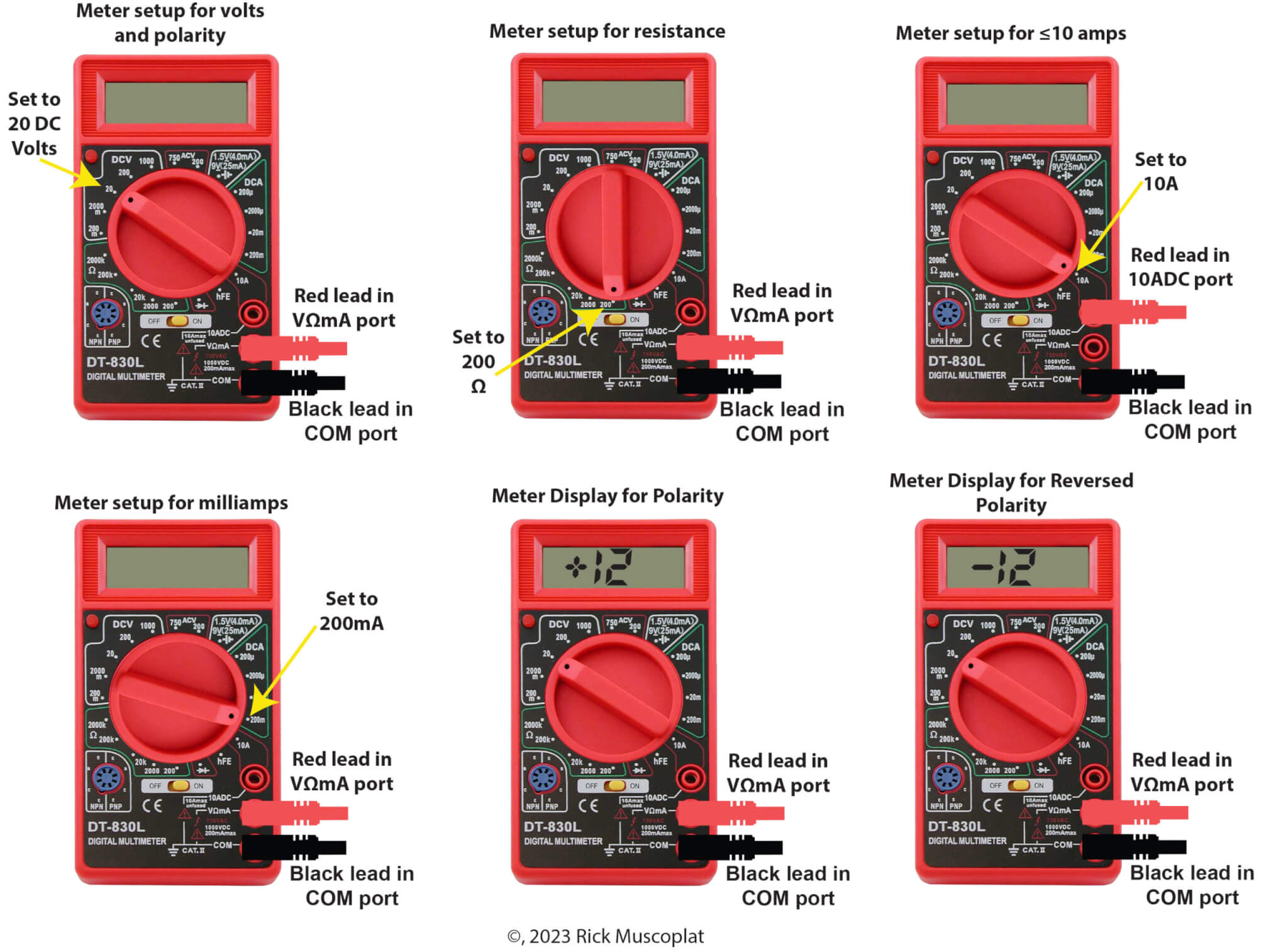
Multimeter setup for volts and polarity (top row left image in the above photo)
Automotive voltage testing is usually done with the meter set to DC volts or DCV. Since auto voltage is usually below 15.5 volts, set the meter dial to the 20 DCV setting. Plug the red lead into the VΩmA port and the black lead into the common (COM) port.
Multimeter setup for Ohms (Ω) resistance/continuity (top row middle image in the above photo)
Automotive resistance for sensor is often fairly low so it’s usually best to start testing with your meter at the lowest Ω setting. In this case the meter is set to 200 Ω. Plug the red lead into the VΩmA port and the black lead into the common (COM) port.
Multimeter setup for 10 or less amps (top row right image in the above photo)
There are very few instances of using this setting in auto-diagnostic work. That’s because auto electrical accessories you might want to currently test will usually draw more than 10 amps. Most multimeters are limited to reading a maximum of 10 amps. If the component draws more than that, you will blow the internal fuse in your meter. When testing high-draw accessories like blower motors, wiper motors, seat heaters, and rear window defoggers, professionals use an inductive clamp because their meters simply can’t handle those higher current draws.
However, if you’re using your meter to test less than 10-amps, set the meter to the 10A setting and move the red lead to the 10ADC port. More on how to connect the leads in series shown below.
Multimeter setup for milliamps (mA) (bottom row left image in the above photo)
When auto computers go into sleep mode, they usually draw less than 50 mA, so set your meter to the 200DCA setting. Plug the red lead into the VΩmA port and the black lead into the common (COM) port.
Multimeter setup for polarity testing (bottom row middle and right image in above photo)
If you’re not sure which of two wires in a connector is battery voltage, set the meter to 20-DCV and connect the red and black leads to the two wires. If the red lead is connected to the battery voltage, the meter will read +12. If you see -12, the black lead is connected to the battery voltage. More on this below.
How to use a multimeter to read power, ground, and polarity
In this example, I’ll use a two-wire connector for a blower motor. The goal is to determine if the blower motor is getting power and ground. The meter is set to 20-DCV. With the key in the RUN position and the fan, switch turned to high, connect the red and black leads to the two terminals in the connector. If the terminal with the red lead is battery voltage, you’ll see +12 on the display. If the terminal touching the black lead is battery voltage, you’ll see -12.
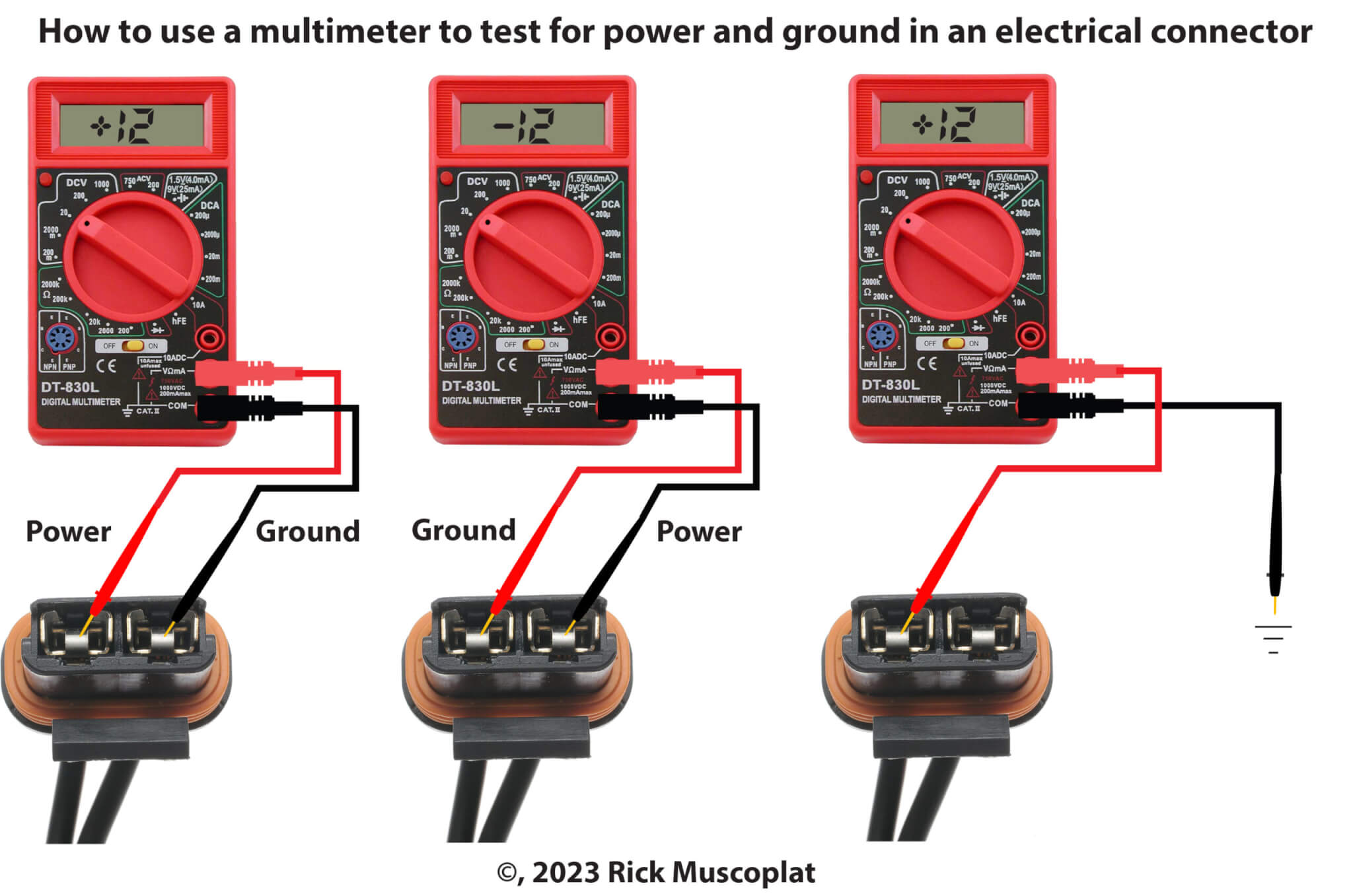
How to use a multimeter to check for power and ground
Another way to test for voltage and polarity is to connect the black lead to a good ground and touch the red lead to each terminal. When the display reads +12, that’s the battery voltage positive wire.
How to use a multimeter to read resistance (ohms)
In this example, we’ll test the resistance of an engine coolant temperature sensor using the Ω scale on the meter. You would test the ohm reading and use a chart from the shop manual to see what temperature the resistance values compare to. Then, you would check the actual temperature of the engine to see if the sensor is off.
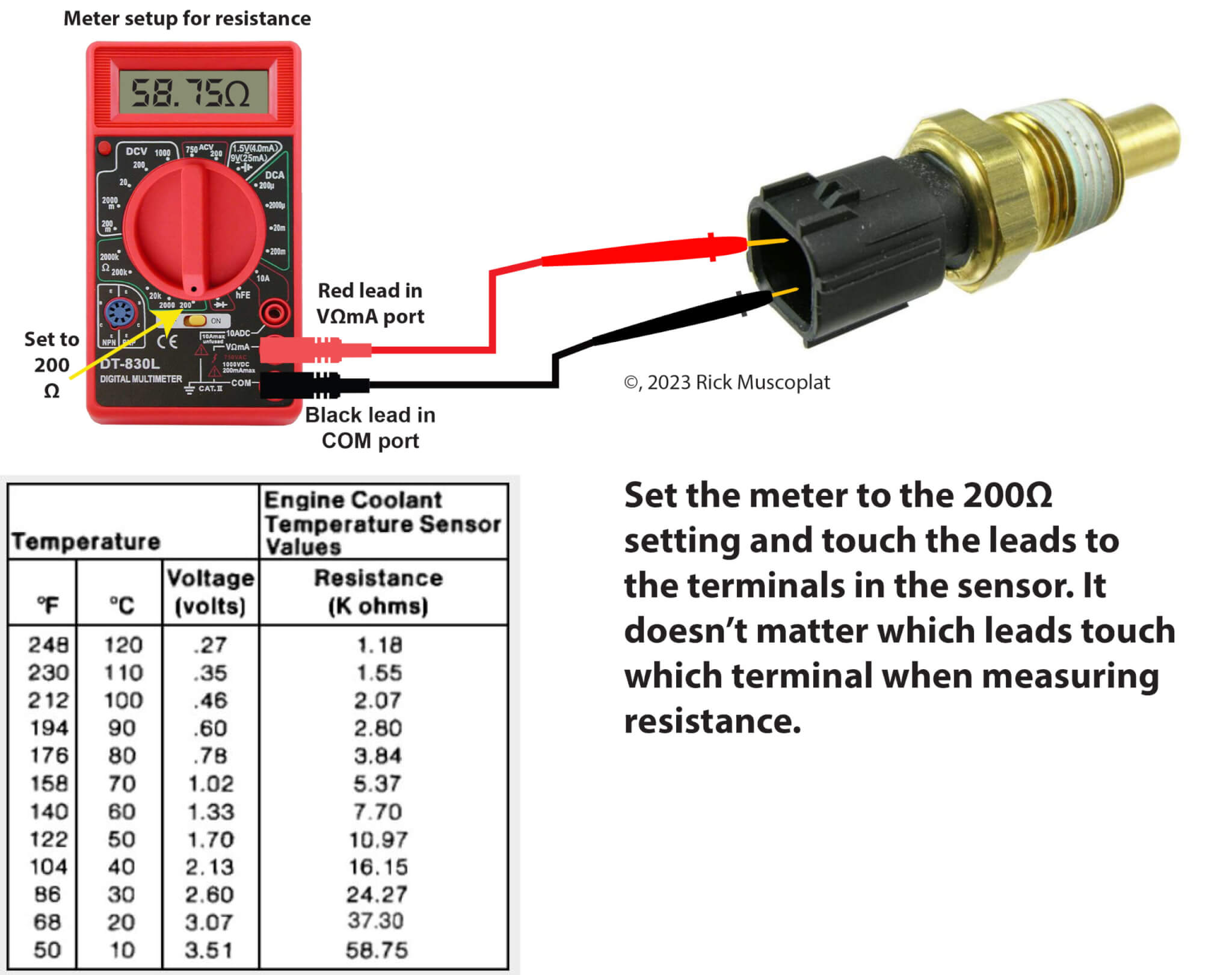
How to use a multimeter to test for resistance
How to use a multimeter to test current draw (less than 10 amps)
A multimeter can only read current draw when connected in series with the power and the device. In this example, we’re testing the current draw on a blend door actuator motor (rated at less than 10 amps). Set the meter to the 10A setting. Plug the red lead into the 10ADC port and the probe to the power source (usually the HVAC controller, but a relay in this example). Then, connect the black lead to the power side of the blend door actuator motor. The power will flow through the meter on its way to the actuator and the display will show the current draw in amps.
WARNING: Maximum amperage is 10 amps. If the device draws more than 10 amps, the internal fuse will blow
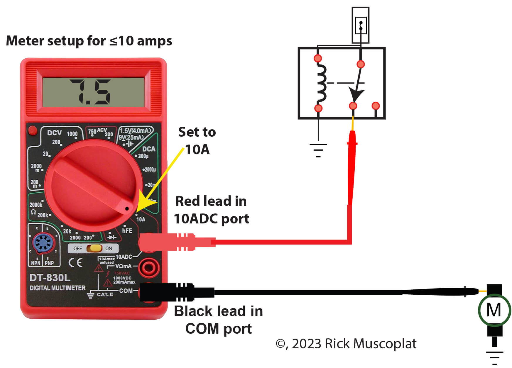
How to use a multimeter to check for current draw
How to use a multimeter to test current draw in milliamps
This is a common test for finding parasitic battery drain. Follow the steps in this post to make sure all the modules are in sleep mode so you don’t exceed the 10-amp limit on your meter.
Set the meter to the 200mA setting. Plug the red lead into the VΩmA port and the black lead into the common (COM) port.
The meter must be installed in series with the negative battery cable. Disconnect the negative cable and connect the red lead to the negative battery post. Connect the black lead to the negative battery terminal.
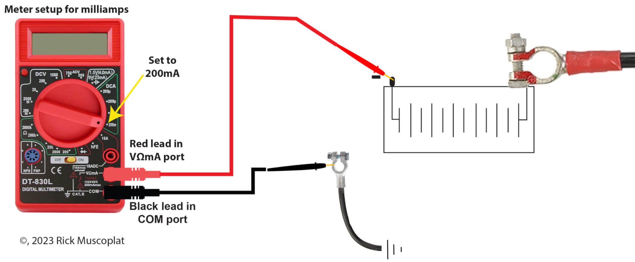
How to use a multimeter to check for milliamp current draw
©, 2023 Rick Muscoplat
Posted on by Rick Muscoplat