P0715 Hyundai
Fix a P0715 Hyundai transmission input speed sensor code
If you come up with a P0715 Hyundai trouble code, here’s how to proceed. The
P0715 — Input/Turbine Speed Sensor “A” Circuit is usually easy to diagnose and fix.
The input turbine speed sensor detects rotation of the input shaft of the

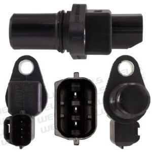
Hyundai input shaft speed sensor
transmission. The computer uses that information, along with the output shaft speed sensor to determine if the transmission is operating according to plan. If the computer detects a difference between the input shaft speed , and the expected output shaft speed, it will adjust transmission pump pressure to prevent clutch disc slip. If adding pressure doesn’t solve the problem, it will set a trouble code.
In the case of a P0715 Hyundai the computer checks the input speed sensor once the transmission is in a forward drive gear, RPM’s are less than 2600, transmission fluid temp sensor is above 4.5-volts, and vehicle speed is over 18.6-MPH. If the computer sees no input speed signal for more than 1-sec, it will set the code and put the transmission into fail-safe mode by locking it into 2nd or 3rd gear.
If you have a scan tool with live data, check the readings from the input sensor with the transmission warmed up and moving. If the sensor reports 0-mph, proceed with the following tests.

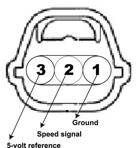
Electrical connector for transmission input speed sensor
Check for reference voltage
The sensor can fail by not getting power, shorting to ground, or by an internal short or open. The sensor has three wires; reference voltage, sensor signal, and ground. With the key in the RUN position, you should see 5-volts on the reference supply terminal (3) of the harness connector and ground. If you don’t see 5-volts, check for open in the wiring harness from the computer.
Measure resistance
With the key in the RUN position, you should see 0-ohms between terminal 1 and chassis ground. Next, check resistance between terminals 1->2, 2->3, and 1->3. Resistance should be above 4-Mohms.
If the sensor fails any of these tests, replace the sensor.
©, 2015 Rick Muscoplat
Posted on by Rick Muscoplat