
2001 Explorer Fuse Box Diagram: Exploring the Fuse Boxes
2001 Explorer Fuse Box Diagram: Find the correct fuse for the circuit
This 2001 Explorer Fuse Box Diagram article shows two fuse boxes. The power distribution box is also called the battery junction box and is located under the hood on the driver’s side near the firewall. It’s a rectangular box next to the brake master cylinder. The fuse and relays for the higher-powered devices are located in that fuse box.
The Passenger Compartment Fuse Box is also called the Central Junction Box. This fuse box is located at the end of the dash board on the driver’s side, covered by a trim panel. To access the fuse box, pull the trim panel toward the door.
To learn more about automotive fuses, see this article
To learn how to check a fuse visually or without removing it, see this article
Find the most commonly replaced fuses here
The fuse box diagram and table below show all 62 fuses and all the relays. But most DIYers are looking for fuses and relays for the lights, power ports, and the blower motor. I’ve listed the most commonly checked/replaced fuses here to save time. I’ve also listed the most commonly replaced bulbs. A blown fuse or bulb are the two most common reasons for lighting issues.
Passenger Compartment Fuse Box = (PCFB) Power Distribution Box (PDB)
• Backup Light: Fuse #27 15A (PCFB)
• Blower Motor: Fuse #2 7.5A (PCFB), Blower Motor Relay #9 in (PDB), Rear Blower Motor #6 7.5A (PCFB), Rear Blower Motor w/EATC temp control #35 7.5A (PCFB), Blower motor relay fuse #2 40A (PDB)
• Front Parking Lamps: Fuse 30 15A (BCM)
• Headlight Low Beam Passenger Side: Fuse #8 10A (PCFB)
• Headlight Low Beam Driver’s Side: Fuse #4 10A (PCFB)
• Headlights High Beam: Fuse #12 30A (PDB)
• Horn: Fuse #10 15A (PDB)
• Power Windows Fuse #4 30A (PDB)
• Parking lamps: Fuse #11 15A (PDB)
• Power Ports: Cigar lighter Fuse #17 25A (PCFB)
•Right turn signals and stop lamps Fuse #7 7.5A (PDB)
•Left Turn Signals and stop lamps Fuse #3 7.5A (PDB)
A note about fuses, battery power and keep alive memory
If you disconnect the battery or remove the PCM fuses from the fuse box, the PCM will lose its adaptive memory and baseline throttle body position. You can avoid this by providing backup power using a jumper pack and an inexpensive OBDII cable. See this article for more information on providing backup power to prevent the loss of adaptive memory. Or, you can perform a throttle body relearn procedure and then drive the vehicle so it can relearn the new adaptive memory settings. See this article for instructions on how to perform a 2014 F150 throttle body relearn procedure.
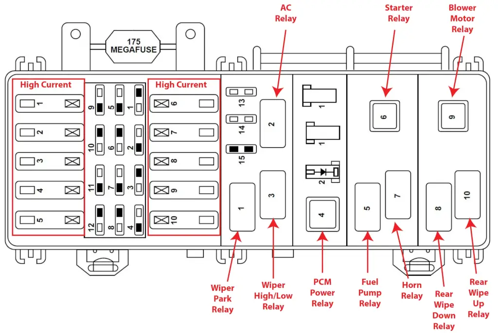
2001 Explorer Fuse Box Diagram for Battery Junction Box/Power Distribution Box
The power distribution box is located in the engine compartment on the driver’s side. Find it near the firewall next to the master cylinder and wiper motor. The power distribution box contains high-current fuses that protect your vehicle’s main electrical systems from overloads.
How to find your fuse and the devices served by that fuse
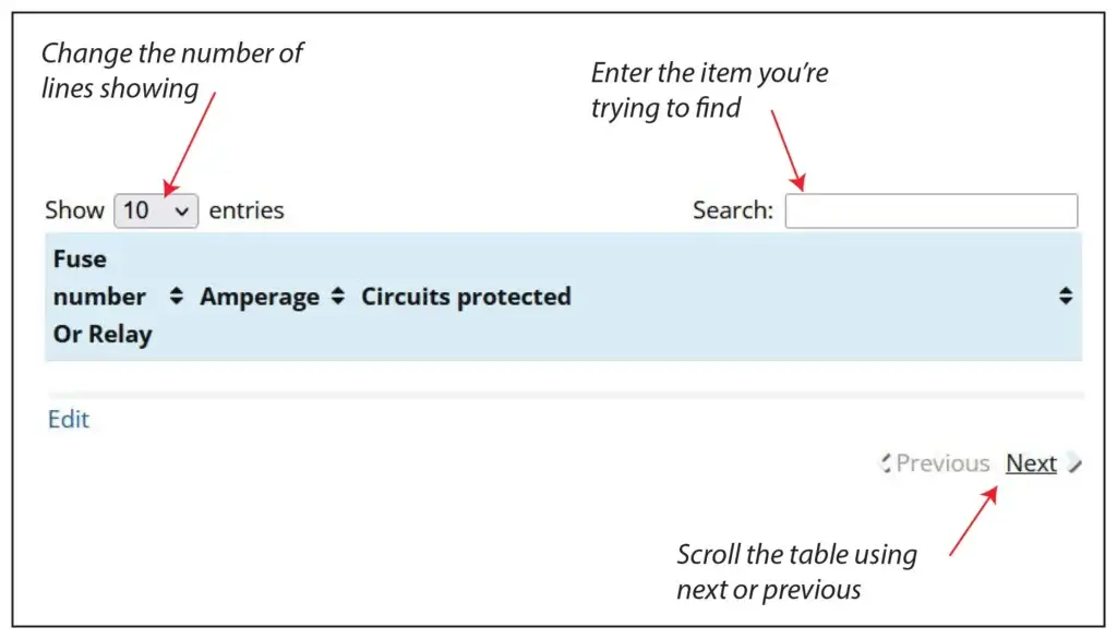
There are 40 fuse/relay slots in the Battery Junction Box. The chart shows only 10 to speed up load time. Here’s how to find the fuse and circuit you want.
1) Change the number of entries showing (in the Show Entries Box) to 100 and scroll the list.
2) Enter the name of the component you’re searching for in the Search box.
3) Use the Next/Previous buttons at the bottom of the table
| Fuse number | Amperage | Circuits protected |
|---|---|---|
| High Current Fuses | ||
| F1 | 60 | I/P Fuse Panel Fuses 1, 9, and 13 |
| F2 | 40 | Blower Motor Relay |
| F3 | 50 | 4 Wheel Anti-Lock Brake System (4WABS) Module |
| F4 | 30 | Power Windows, Power Moon Roof, Power Seat |
| F5 | 50 | Ignition Switch, Starter Relay |
| F6 | 20 | Transfer Case Relay |
| F7 | — | Not Used |
| F8 | 20 | Air Suspension |
| F9 | 40 | Air Suspension |
| F10 | 30 | PCM Power Relay |
| Regular Fuses | ||
| F1 | 10 | A/C Relay |
| F2 | 30 | Heated Seats |
| F3 | 30 | Heated Backlight |
| F4 | 15 | Fog Lamps and Daytime Running Lamps |
| F5 | — | Not Used |
| F6 | 10 | Powertrain Control Module |
| F7 | 30 | 4 Wheel Anti-Lock System (4WABS) Module |
| F8 | 15 | Rear Wiper Motor |
| F9 | 20 | Fuel Pump Relay and RAP Module |
| F10 | 15 | Horn Relay |
| F11 | 15 | Parklamps Relay and Mainlight Switch |
| F12 | 30 | Mainlight Switch and Multifunction Switch |
| F14 | 15 | Heated Oxygen Sensor, EGR Vacuum Regulator, EVR Solenoid, Camshaft Position (CMP) Sensor, Canister Vent Solenoid |
| F14 | 30 | Generator/Voltage Regulator |
| F15 | — | Not Used |
| Relays | ||
| 1 | — | Wiper Park Relay |
| 2 | — | A/C Relay |
| 3 | — | Wiper High/Low Relay |
| 4 | — | PCM Power Relay |
| 5 | — | Fuel Pump Relay |
| 6 | — | Starter Relay |
| 7 | — | Horn Relay |
| 8 | — | Rear Wipe Down Relay |
| 9 | — | Blower Motor Relay |
| 10 | — | Rear Wipe Up Relay |
| 1 | — | Not Used |
| 1 | — | DRL Diode |
| 2 | — | Electronic Engine Controls Diode |
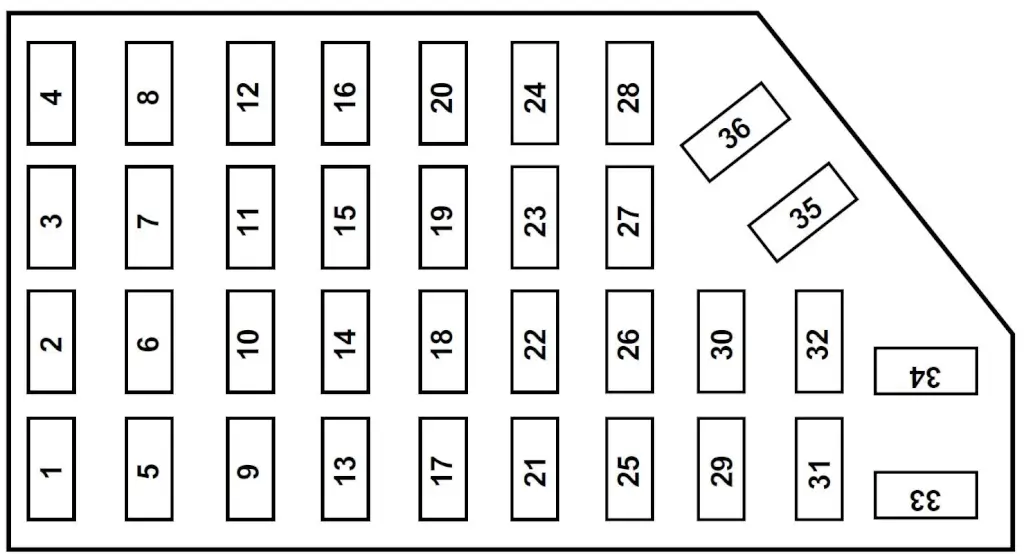
Explorer Fuse Box Diagram for Cabin/Passenger Compartment Fuse Panel
The cabin fuse panel is located on the far left-hand side of the instrument panel. The panel faces the driver’s door and is covered by a snap-in lid. Pull the panel cover outward to access the fuses.
| Fuse number | Amperage | Circuits protected |
|---|---|---|
| F1 | 7.5 | Power Mirror Switch, Power Antenna, Memory Seat |
| F2 | 7.5 | Blower Motor Relay, Air Bag Diagnostic Monitor |
| F3 | 7.5 | Left Stop/Turn Trailer Tow Connector |
| F4 | 10 | Left Headlamp |
| F5 | 10 | Data Link Connector (DLC) |
| F6 | 7.5 | Rear Blower Motor (Without EATC) |
| F7 | 7.5 | Right Stop/Turn Trailer Tow Connector |
| F8 | 10 | Right Headlamp, Foglamp Relay |
| F9 | 7.5 | Brake Pedal Position Switch |
| F10 | 7.5 | Speed Control/Amplifier Assembly, Generic electronic Module (GEM), Shift Lock Actuator, Blend Door Actuator, A/C - Heater Assembly, Flasher, Overhead Console, Load Leveling Module |
| F11 | 7.5 | Instrument Cluster |
| F12 | 7.5 | Washer Pump Relay, Rear Washer Pump Relay |
| F13 | 20 | Brake Pedal Position Switch, Brake Pressure Switch |
| F14 | 10 | 4 Wheel Anti-Lock Brake System (4WABS) Module, 4WABS Main Relay |
| F15 | 7.5 | Instrument Cluster |
| F16 | 30 | Windshield Wiper Motor, Wiper Hi-Lo Relay, Wiper Run/Park Relay |
| F17 | 25 | Cigar Lighter |
| F18 | 25 | Drivers Unlock Relay, All Unlock Relay, All Lock Relay, Power Seats |
| F19 | 25 | PCM Power Diode |
| F20 | 7.5 | RAP Module, Generic Electronic Module (GEM), Radio |
| F21 | 7.5 | Flasher (Hazard) |
| F22 | 20 | Auxiliary Power Socket |
| F23 | — | Not Used |
| F24 | 7.5 | Clutch Pedal Position (CPP) Switch, Starter Interrupt Relay, Anti-Theft |
| F25 | 7.5 | Generic Electronic Module (GEM), Instrument Cluster, Securi-Lock |
| F26 | 10 | Battery Saver Relay, Electronic Shift Relay, Interior Lamp Relay, Electronic Shift Control Module |
| F27 | 15 | DRL, Backup Lamps Switch, DTR Sensor, Electric Shift |
| F28 | 7.5 | Generic Electronic Module (GEM), Radio, Memory Seat |
| F29 | 25 | Radio |
| F30 | 15 | Park Lamp/Trailer Tow Relay |
| F31 | — | Not Used |
| F32 | 10 | Heated Mirror |
| F33 | 15 | Headlamps, Daytime Running Lamps (DRL) Module, Instrument Cluster |
| F34 | 7.5 | Rear Integrated Control Panel, CD |
| F35 | 7.5 | Rear Blower Motor (w/EATC) |
| F36 | 7.5 | EATC Memory, CD, Rear Integrated Control Panel, Memory Seat, Message Center |
Tips to diagnose electrical issues on your 2001 Explorer
If your power windows don’t work
The fuse for the driver’s side power window is #4 30A in the PDB, and the #3 30A for the passenger side window.
If your blower motor doesn’t work
The blower motor gets its power from the blower motor relay #9 in the battery junction/power distribution box.
If the circuit you’re working on contains a relay
• A simple way to test a relay is to swap in a similarly shaped relay and see if the component works.
• If that doesn’t work, remove the relay and test for power to the relay control coil and contacts using a multimeter. For more information on relay testing, see this article.
©, 2018 Rick Muscoplat