
2012 F150 Fuse Diagram: Exploring the Fuse Boxes
2012 F150 Fuse Diagram: Locate all the circuits served by each fuse
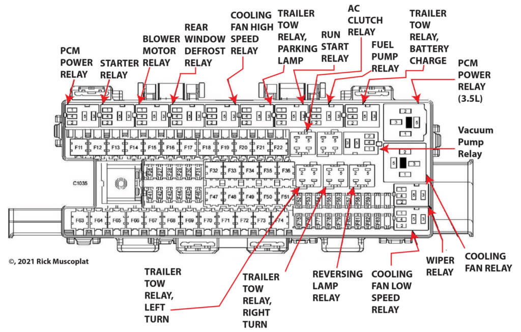
This 2012 Ford F150 Fuse Diagram post shows three fuse boxes; the Battery Junction Box, Power Distribution Box located under the hood and the Body Control Module (BCM)/Passenger Compartment Fuse Panel
To learn more about automotive fuses, see this article
To learn how to check a fuse visually or without removing it, see this article
2012 F150 Fuse Diagram for Battery Junction Box
To learn how to check a fuse visually or without removing it, see this article
How to find your fuse and the devices served by that fuse
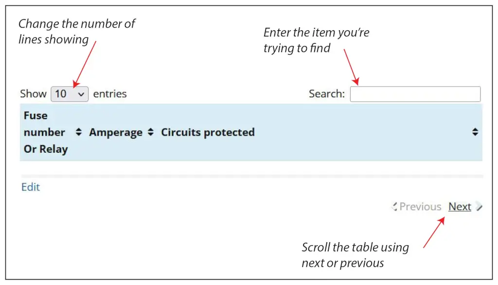
There are 62 fuse slots in the Battery Junction Box. The chart shows only 10 to speed up load time. Here’s how to find the fuse and circuit you want.
1) Change the number of entries showing (in the Show Entries Box) to 100 and scroll the list.
2) Enter the name of the component you’re searching for in the Search box.
3) Use the Next/Previous buttons at the bottom of the table
| Fused number | Amperage | Circuits protected |
|---|---|---|
| F11 | 30 | Power Running Board (PRB) module |
| F12 | 40 | Low Fan Control (LFC) relay |
| F12 | 50 6.2L | Low Fan Control (LFC) relay |
| F13 | 30 | Starter relay |
| F14 | 30 | Seat control switch,passenger side front |
| F15 | 40 | High Fan Control (HFC) relay |
| F15 | 50 6.2L | " |
| F16 | — | Not used |
| F17 | 30 | Trailer Brake Control (TBC) module, Telematics module |
| F18 | 30 | Upfitter relay 1 |
| F19 | 30 | Upfitter relay 2 |
| F20 | 20 | Transfer Case Control Module (TCCM) - with 4x4 |
| F21 | 30 | Trailer tow battery charge relay |
| F22 | 20 | Cigar lighter, front-Power Port |
| F26 | 10 | PCM power relay, Evaporative emission (EVAP) canister vent solenoid, Powertrain Control Module (PCM) |
| F27 | 20 | Fuel pump relay |
| F28 | 10 | Upfitter relay 4 |
| F29 | 10 | Constant Vacuum Hublock (CVH) solenoid |
| F30 | 10 | AC clutch relay |
| F31 | 15 | Run/start relay |
| F32 | 40 | Rear window defrost relay |
| F33 | 40 | DC/AC inverter module |
| F34 | 40 | PCM power relay |
| F34 | 50 3.5L | " |
| F35 | 20 | Headlamp, left (HID) |
| F36 | 30 | Anti-lock Brake System (ABS) module |
| F41 | — | Not used |
| F42 | 5 | Run/start relay |
| F43 | 15 | Reversing lamp relay |
| F44 | 15 | Upfitter relay 3 |
| F45 | 10 | Generator |
| F46 | 10 | Brake Pedal Position (BPP) switch |
| F47 | 60 | Anti-lock Brake System (ABS) module |
| F48 | 20 | Roof opening panel module |
| F49 | 30 | Wiper relay |
| F50 | — | Not used |
| F51 | 40 | Blower motor relay |
| F52 | 5 | Power steering control module (PSCM), Blower motor relay,, **Vacuum pump relay (3.5L) |
| F53 | 5 | Powertrain Control Module (PCM) |
| F54 | 5 | Anti-lock Brake System (ABS) module, Transfer Case Control Module (TCCM), Rear window defrost relay, Trailer tow battery charge relay, Front camera washer relay |
| F55 | — | Not used |
| F56 | 15 | Exterior rear view mirrors |
| F57 | — | Not used |
| F58 | — | Not used |
| F59 | — | Not used |
| F60 | — | Not used |
| F61 | — | Not used |
| F62 | — | Not used |
| F63 | 25 | Cooling fan relay |
| F64 | 40 3.5L only | Vacuum pump relay |
| F65 | 20 | Power port, instrument panel |
| F66 | 20 | Power point, console 1 - with floor shifter |
| F67 | 20 | Trailer tow relay, parking lamp |
| F68 | 20 | Transfer Case Control Module (TCCM) |
| F69 | 30 | Dual Climate Controlled Seat Module (DCSM), Heated seat module |
| F70 | — | Not used |
| F71 | 20 | Heated seat module, left rear |
| F72 | 20 | Power point, console 2 |
| F73 | 20 | Trailer tow relay, left turn, Trailer tow relay, right turn |
| F74 | 30 | Seat control switch, driver side front - without memory Driver Seat Module (DSM) - with memory |
| F75 | 15 | Powertrain Control Module (PCM) |
| F75 | 25 3.5L | Powertrain Control Module (PCM) |
| F76 | 20 | Mass Air Flow / Intake Air Temperature (MAF/IAT) sensor, Variable Camshaft Timing (VCT) solenoids, Heated oxygen sensors (HO2Ss), Universal heated oxygen sensors (HO2Ss), Evaporative emission (EVAP) canister purge valve, Evaporative emission (EVAP) canister vent solenoid |
| F77 | 10 | Cooling fan relays, AC clutch relay |
| F78 | 15 | Coil on Plugs (COPS), Ignition transformer capacitors |
| F78 | 20 3.5L | Coil on Plugs (COPS), Ignition transformer capacitors |
| F79 | 5 | Rain sensor module |
| F80 | — | Not used |
| F81 | — | Not used |
| F82 | — | Not used |
2012 F150 Fuse Diagram for Body Control Module
The battery control module (BCM) is located inside the cabin under the dash. It’s considered a smart junction box, meaning that it receives a request from a switch like a light switch or a door switch and then switches power to that device.
In other words, the switch doesn’t actually switch power to the device. The switch closure just acts as an input or a request to the BCM. By using very low-current wire between the switches and the BCM, carmakers save on wiring costs and lower the vehicle’s weight.
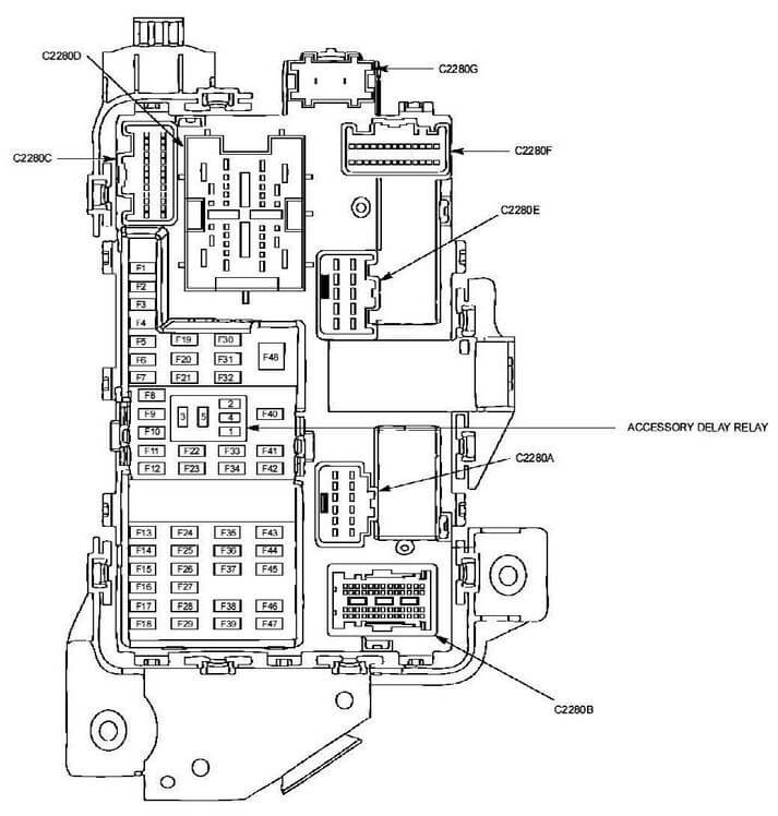
The BCM has 48 fuse slots, but the chart shows only 10 to speed up load time. Here’s how to find the fuse and circuit you want.
1) Change the number of entries showing (in the Show Entries Box) to 50 and scroll the list.
2) Enter the name of the component you’re searching for in the Search box.
3) Use the Next/Previous buttons at the bottom of the table
| Fuse number | Amperage | Circuits protected |
|---|---|---|
| F1 | 30 | Power window motor left front |
| F2 | 15 | Accessory Protocol Interface Module (APIM) |
| F3 | 30 | Power window motor, right front |
| F4 | 10 | Tool link reader, Battery saver relay, Dome lamp, front Vanity mirror lamps, Interior map/lamps |
| F5 | 20 | Seat control switch, driver side front-with memory |
| F6 | — | Not used |
| F7 | 7.5 | Exterior rearview mirror switch, Driver Seat Module (DSM) |
| F8 | — | Not used |
| F9 | 10 | Front Display Interface Module (FDIM) - without navigation, Front Controls Interface Module (FCIM), Global Positioning System Module (GPSM) - with SYNC |
| F10 | 10 | Run/acc relay |
| F11 | 10 | Instrument Panel Cluster (IPC) |
| F12 | 15 | High mounted stop lamp, Exterior rearview mirrors, Interior map/lamps, Dome lamp, front, Ambient lighting switch, Floor shifter, Upfitter switch, Hill descent control switch, Off-road mode switch, Overhead console switch assembly, Hazard/pad/traction switch, Headlamp switch, Instrument panel dimming switch, Audio Control Module (ACM), Mode Select Switch (MSS), Steering wheel switches, In-dash computer |
| F13 | 15 | Park/turn lamps, Trailer tow relay, right turn, Park/stop/turn lamps, right rear |
| F14 | 15 | Park/turn lamps, Trailer tow relay, left turn, Park/stop/turn lamps, left rear |
| F15 | 15 | High mounted stop lamp, Reversing lamp relay, Reversing lamps, Auto-dimming interior mirror |
| F16 | 10 | Right headlamp - low beam |
| F17 | 10 | Left headlamp - low beam |
| F18 | 10 | Brake shift interlock, Passive anti-theft transceiver, Floor shifter, Powertrain Control Module (PCM), Keyless entry keypad |
| F19 | 20 | Audio Digital Signal Processing (DSP) module |
| F20 | 20 | Door latch actuators |
| F21 | 10 | Interior Lighting Control Module (ILCM) |
| F22 | 20 | Horn relay |
| F23 | 15 | Steering Column Control Module (SCCM) |
| F24 | 15 | Data Link Connector (DLC), Steering Column Control Module (SCCM) |
| F25 | — | Not used |
| F26 | 5 | Tire Pressure Monitor (TPM) module |
| F27 | — | Not used |
| F28 | 15 | Ignition switch |
| F29 | 20 | Audio Control Module (ACM), In-dash computer |
| F31 | 5 | Trailer Brake Control (TBC) module, Brake Pedal Position (BPP) switch, Powertrain Control Module (PCM) |
| F32 | 15 | Roof opening panel module, Door lock switches, Master window control 5 Power window motors, Window control switch, passenger side, Electronic compass, Auto-dimming interior mirror, Heated seat switches |
| F33 | 10 | Heated seat module |
| F34 | 10 | Parking Aid Module (PAM), Video camera, Off-road mode switch, Mode Select Switch (MSS) |
| F37 | 10 | Trailer Brake Control (TBC) module, Telematics module |
| F38 | 10 | DC/AC inverter module, Audio Control Module (ACM), In-dash computer |
| F39 | 15 | Headlamps - high beam |
| F40 | 10 | Trailer tow relay, parking lamps, License plate lamps, Park/stop/turn lamps, Marker lamps |
| F41 | 7.5 | Hazard/pad/traction switch, Upfitter switch |
| F42 | 5 | Tow haul switch, Floor shifter |
| F43 | — | Not used |
| F44 | — | Not used |
| F45 | — | Not used |
| F46 | 10 | HVAC module |
| F47 | 15 | Fog lamp relay, Exterior rearview mirror, passenger side Exterior rearview mirror, driver side |
| F48 | 30A Circuit Breaker | Master window control switch, Overhead console switch |
2012 F150 Fuse Diagram for High Current Battery Junction Box
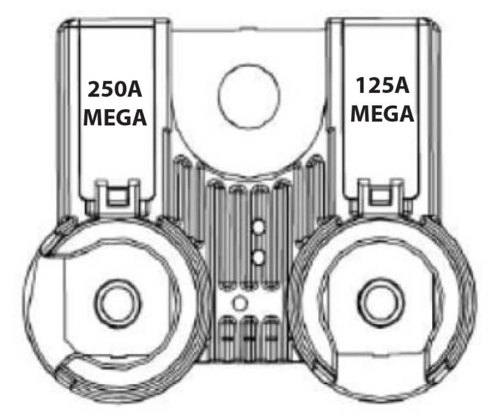
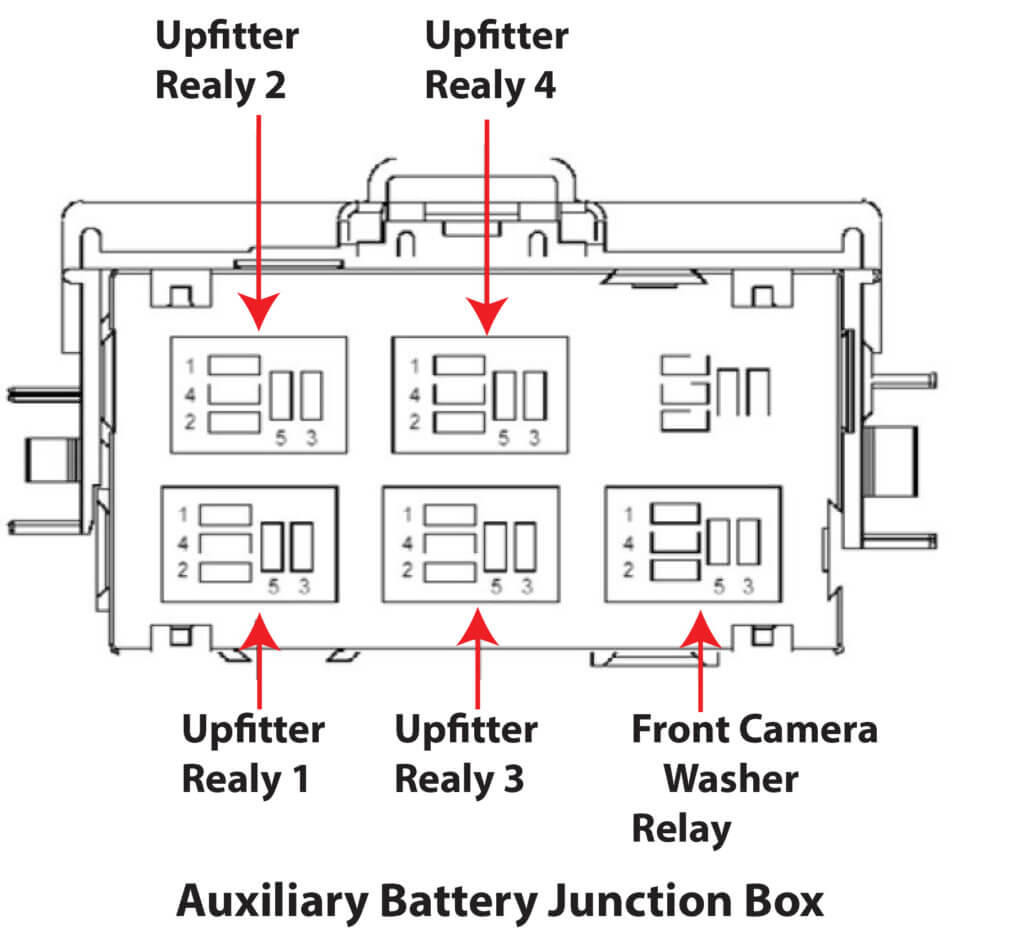
2012 F150 Fuse Diagram for Auxiliary Battery Junction Box
Looking for more information on your 2012 F150? Click here for the Firing Order, Engine Layout Diagram, Spark Plug Gap and Spark Plug Torque specs.
Posted on by Rick Muscoplat