
2012 Mustang Fuse Box Diagram
2012 Mustang Fuse Box Diagram: Exploring the Fuse Boxes
In this article, you’ll see the 2012 Mustang fuse box diagrams for the battery junction box/power distribution box under the hood, as well as the passenger compartment fuse box/body control module (BCM)/smart junction box located under the dash on the passenger side of the vehicle.
Let’s start with the one under the hood. It’s located near the front of the engine compartment on the passenger side. The power distribution box is like the nerve center for your truck’s major systems—things like engine management, emissions, and ABS brakes are all controlled by the fuses in this box.
Now, for the second fuse box, crawl under the dash on the passenger side. The passenger compartment fuse box is located in the footwell area, on the passenger side, and behind the kick panel. This fuse box takes care of all the interior electrical stuff like the radio, power windows/locks, climate controls, and those handy courtesy lights. It’s essential to give both of these fuse boxes a once-over every so often to make sure none of the fuses are blown. If your electrical gadgets aren’t acting right, it might be a sign that something’s amiss with the fuses.
To learn more about automotive fuses, see this article
To learn how to check a fuse visually or without removing it, see this article
Find the most commonly replaced fuses and bulbs here
The fuse box diagram and table below show all 62 fuses and all the relays. But most DIYers are looking for fuses and relays for the lights, power ports, and the blower motor. I’ve listed the most commonly checked/replaced fuses here to save time. I’ve also listed the most commonly replaced bulbs. A blown fuse or bulb are the two most common reasons for lighting issues.
Power Distribution Box = PDB, Passenger Compartment Fuse Box = PCFB
• Turn signals/Hazards: Fuse #6 20A PCFB
• Parking Lamps: Fuse #22 15A PCFB
• Driver Side Low Beam Headlight: Fuse #7 10A PCFB
• Passenger Side Low Beam Headlight: Fuse #8 10A PCFB
• High Beam Headlights (Both Sides): fuse #23 15A PCFB
• Horn: Fuse #24 20A PCFB
• Power Point: Fuse #5 20A PDB
• Passenger Power Window: Fuse #29 30A PDB
• Driver Power Window: Fuse #34 30A PDB
• Blower Motor: Fuse #4 30A PDB
How to find your fuse and the devices served by that fuse
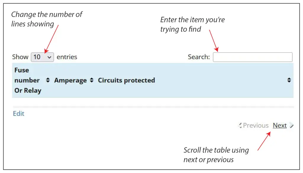
There are 62 fuses in the Battery Junction Box. There are several ways to find the fuse you want in the chart below.
1) Enter the number in the search box. That’s the fastest way
2) If you’d like to scroll all the fuses, change the Number of entries to show on the page in “Show Entries” box. Click NEXT or PREVIOUS at the bottom right of the table
2012 Mustang Fuse Box Diagram for Power Distribution Box

2012 Mustang underhood fuse box diagram
| Fuse Number | Amperage | Circuits Protected |
|---|---|---|
| F1 | 😯 | Passenger compartment fuse panel, Smart Junction Box (SJB) |
| F2 | — | Not used |
| F3 | — | Not used |
| F4 | 30 | Blower motor relay |
| F5 | 20 | Power point |
| F6 | 40 | Rear defroster |
| F7 | 40 | High and Low speed engine cooling fan relays |
| F8 | 40 | nti-lock Brake System (ABS) module |
| F9 | 30 | Wiper relay |
| F10 | 30 | Anti-lock Brake System (ABS) module |
| F11 | — | Not used |
| F12 | — | Not used |
| F13 | 20/25 | Fuel pump relay (non-Shelby)/Fuel pump relay (Shelby only) |
| F14 | — | Not used |
| F15 | 10 | Intercooler pump relay (Shelby only) |
| F16 | 20 | Heated seats |
| F17 | 10 | Alternator sense |
| F18 | 20 | Auxiliary body module (ABM) |
| F19 | 30 | Starter relay |
| F20 | 30 | Rear amplifier (Shaker 1000 radio) |
| F21 | 30 | Powertrain relay |
| F22 | 20 | Powerpoint (instrument panel) |
| F23 | 10 | Powertrain control module (PCM) keep-alive power |
| F24 | 10 | Brake on/off (BOO) power |
| F25 | 10 | A/C compressor relay |
| F26 | 20 | Left high intensity discharge headlamp relay |
| F27 | 20 | Right high intensity discharge headlamp relay |
| F28 | — | Not used |
| F29 | 30 | Passenger front window |
| F30 | — | Not used |
| F31 | 30 | Passenger power seat |
| F32 | 30 | Driver power seat |
| F33 | 30 | Front amplifier (Shaker 500 radio) |
| F34 | 30 | Driver front window motor |
| F35 | 40 | Convertible top motor |
| F36 | Diode | Fuel diode |
| F37 | — | Not used |
| F38 | 15 | Fuel injectors (Shelby only) |
| F39 | 5 | Rear defroster coil (run/start) |
| F40 | 15 | PCM vehicle power 4 – ignition coil |
| F41 | G8VA relay | Fuel pump relay |
| F42 | G8VA relay | Intercooler pump relay (Shelby only) |
| F43 | G8VA relay | A/C compressor relay |
| F44 | — | Not used (spare) |
| F45 | 5 | PCM run/start |
| F46 | 5 | PCM vehicle power 3 – general powertrain components |
| F47 | 15 | PCM vehicle power 1 |
| F48 | 15 | Mass air flow sensor |
| F49 | 15 | PCM vehicle power 2 – emissions related powertrain components |
| F50 | Full ISO relay | Cooling fan relay (high) |
| F51 | Full ISO relay | Blower motor relay |
| F52 | Full ISO relay | Starter relay |
| F53 | Full ISO relay | Rear defroster relay |
| F54 | Full ISO relay | Front wiper relay |
| F55 | Full ISO relay | Cooling fan relay (low) |
| F56 | High current relay | Fuel pump sensor (Shelby only) |
| F57 | Full ISO relay | PCM relay |
| F58 | High current relay | Not used (Spare) |
A note about fuses, battery power and keep alive memory
If you disconnect the battery or remove the PCM fuses from the fuse box, the PCM will lose its adaptive memory and baseline throttle body position. You can avoid this by providing backup power using a jumper pack and an inexpensive OBDII cable. See this article for more information on providing backup power to prevent the loss of adaptive memory. Or, you can perform a throttle body relearn procedure and then drive the vehicle so it can relearn the new adaptive memory settings. See this article for instructions on how to perform a 2012 Mustang throttle body relearn procedure.
2012 Mustang Fuse Box Diagram for Smart Junction Box

2012 Mustang Passenger Compartment Fuse Box Diagram
| Fuse Number | Amperage | Circuits Protected |
|---|---|---|
| F1 | 30 | Driver rear window (convertible only) |
| F2 | 15A | Not used (spare) |
| F3 | 15 | Accessory Protocol Interface Module (APIM |
| F4 | 30 | Passenger rear window (convertible only) |
| F5 | 10 | Brake transmission shift interlock (BTSI) |
| F6 | 20 | Turn signals, Hazard flashers |
| F7 | 10 | Left low beam headlamp |
| F8 | 10 | Right low beam headlamp |
| F9 | 15 | Courtesy lamps |
| F10 | 15 | Switch illumination |
| F11 | 10 | Security module |
| F12 | 7.5 | Power mirrors |
| F13 | 5A | Not used (spare) |
| F14 | 10 | Center information display, Electronic finish panel, GPS |
| F15 | 10 | Climate control |
| F16 | 15 | Not used (spare) |
| F17 | 20 | Power door locks, Trunk release |
| F18 | 20 | Not used (spare) |
| F19 | 25 | Navigation amp/Audio amplifier |
| F20 | 25 | Diagnostic connector |
| F21 | 15 | Fog lamps |
| F22 | 15 | Park lamps, License lamps |
| F23 | 15 | High beam headlamps |
| F24 | 20 | Horn |
| F25 | 10 | Demand lighting (battery saver), Gauge pack, Visor vanity lamps |
| F26 | 10 | Instrument Panel Cluster (IPC) |
| F27 | 20 | Ignition switch feed |
| F28 | 5 | Audio Control Module (ACM) |
| F29 | 5 | Camera (run/start) |
| F30 | 5 | Temperature sensor motor |
| F31 | 10 | Restraints control module (RCM) |
| F32 | 10 | Reverse parking aid |
| F33 | 10 | Not used (spare) |
| F34 | 5 | Electronic stability control |
| F35 | 10 | Auxiliary body module (ABM) run/start |
| F36 | 5 | Passive anti-theft system (PATS) |
| F37 | 10 | Not used (spare) |
| F38 | 20 | Not used (spare) |
| F39 | 20 | Radio/Navigation |
| F40 | 20 | Not used (spare) |
| F41 | 15 | Accessory delay (windows, automatic dimming rear view mirror [including microphone and compass] and door switch III) |
| F42 | 10 | Not used (spare) |
| F43 | 10 | Heated seat relay coils |
| F44 | 10 | Not used (spare) |
| F45 | 5 | Wiper relay and module, Blower relay |
| F46 | 7.5 | Passenger airbag deactivation indicator (PADI), Occupant classification sensor (OCS) |
| F47 | 30A Circuit Breaker | Not used (spare) |
| F48 | Relay | Accessory delay relay (windows, automatic dimming rear view mirror [including microphone and compass] and door switch III) |
Tips to diagnose electrical issues on your 2012 Mustang
If your power windows don’t work
• Ford uses a 30A circuit fuse for each window.
The fuse for the driver’s side power window is Fuse #34 30A PDB, and the fuse for the passenger side window is Fuse #29 30A PDB.
If your blower motor doesn’t work
The blower motor gets its power from the blower motor relay ##51 in the power distribution box.
If the circuit you’re working on contains a relay
• A simple way to test a relay is to swap in a similarly shaped relay and see if the component works.
• If that doesn’t work, remove the relay and test for power to the relay control coil and contacts using a multimeter. For more information on relay testing, see this article.
©, 2018 Rick Muscoplat