
2014 Ram Pickup Fuse Box Diagram: Exploring the Fuse Boxes
2014 Ram Pickup Fuse Box Diagram
2014 Dodge Ram Pickup Fuse Box Diagram for PDC
2014 Ram Pickup Fuse Box Diagram for Power Distribution Center
2014 Ram Fuse Box Diagram power distribution center
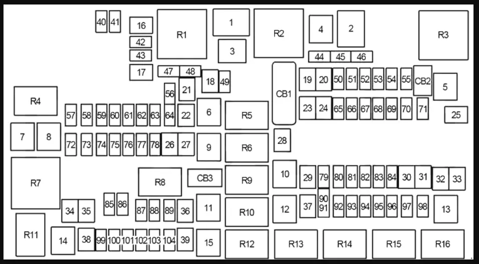
Underhood Fuses (Power Distribution Center)
Location of the Power Distribution Center: In the engine compartment near the battery. The PDC contains cartridge fuses and mini fuses, relays and circuit breakers
Fuses in the PDC
01 80A Rad Fan Control Module – If equipped
03 60A Rad Fan – If equipped
05 40A Compressor for Air Suspension – If equipped
06 40A Antilock Brakes / Electronic Stability Control Pump
07 40A Starter Solenoid
08 30A Emissions Diesel – If equipped
09 40A Diesel Fuel Heater – If equipped
10 40A Body Controller / Exterior Lighting #2
10 50A Body Controller / Exterior Lighting #2 – If equipped with Start/Start
11 30A Integrated Trailer Brake Module – If equipped
12 40A Body Controller #3 / Interior Lights
13 40A Blower Motor
14 40A Body Controller #4 / Power Locks
15 30A Electric Park Brake Right Side – If equipped
19 30A SCR – If equipped
20 30A Passenger Door Module
21 30A Drive Train Control Module
22 20A Engine Control Module
23 30A Body Controller #1
24 30A Driver Door Module
25 30A Front Wiper Low Speed
25 30A Front Wiper High Speed
26 30A Antilock Brakes / Stability Control / Valves
28 20A Trailer Tow Backup Lights – If equipped
29 20A Trailer Tow Parking Lights – If equipped
30 30A Trailer Tow Receptacle – If equipped
32 30A Drive Train Control Module – If equipped
33 20A Diesel Fuel Heater #1 – if equipped / Rear Blower – If equipped
34 30A Vehicle System Interface Module #2 – If equipped
35 30A Sunroof – If equipped
36 30A Rear Defroster – If equipped
37 30A Diesel Fuel Heater #2 – If equipped
38 30A Power Inverter 115V AC – If equipped
39 30A Vehicle System Interface Module #1 – If equipped
41 10A Active Grill Shutter
42 20A Horn
43 10A Snow Plow Left – If equipped
44 10A Diagnostic Port
46 10A Tire Pressure Monitor
47 10A Snow Plow Right – If equipped
49 10A Instrument Panel Cluster
50 20A Air Suspension Control Module – If equipped
51 10A Ignition Node Module / Keyless Ignition
52 5A Battery Sensor
53 20A Trailer Tow – Left Turn/Stop Lights
54 20A Adjustable Pedals
55 20A E38 Radio – If Equipped
56 15A Additional Diesel Content – If Equipped
57 20A (Gas Engine) / 25A (Diesel Engine) Transmission
58 20A Engine Cooling Pump
60 15A Underhood Lamp
61 20A Power Take-off Unit if equipped
62 10A Air Conditioning Clutch
63 20A Ignition Coils (Gas), Urea Heater (Diesel)
64 25A Fuel Injectors / Powertrain
65 10A USB interface
66 10A Sunroof / Passenger Window Switches / Rain Sensor
67 10A CD / DVD / Bluetooth Hands-free Module – If equipped
69 15A Mod SCR 12V – If equipped
70 30A Fuel Pump Motor
71 25A Amplifier
72 10A Voltage Stabilizer Modules – If equipped
74 20A (Gas Engine) / 10A (Diesel Engine) Brake Vacuum Pump Gas/Diesel – If equipped
75 10A Coolant Temperature Valve Actuator
76 10A Antilock Brakes/Electronic Stability Control
77 10A Drivetrain Control Module/Front Axle Disconnect Module
78 10A Engine Control Module / Electric Power Steering
79 15A Clearance Lights
80 10A Universal Garage Door Opener / Compass
81 20A Trailer Tow Right Turn/Stop Lights
82 10A Steering Column Control Module/ Cruise Control
84 15A Switch Bank/Instrument Cluster
85 10A Airbag Module
86 10A Airbag Module
87 10A Air Suspension / Trailer Tow / Steering Column Control Module
88 15A Instrument Panel Cluster
90/F91 20A Power Outlet (Rear seats) Customer Selectable
93 20A Cigar Lighter
94 10A Shifter / Transfer Case Module
95 10A Rear Camera / Park Assist
96 10A Rear Seat Heater Switch
97 25A Rear Heated Seats & Heated Steering Wheel – If equipped
98 25A Front Heated Seats if equipped
99 10A Climate Control
101 15A Electrochromatic Mirror/Smart High Beams – If equipped
104 20A Power Outlets (Instrument Panel/Center Console)
Circuit breakers in the PDC
CB1 25A Power Windows
CB2 25A Power Seat Driver / Memory Seat Module – If equipped
CB3 25A Power Seat Passenger
Relays in the PDC
08 Run Start
09 Fuel Heated
10 EBL
11 Starter #1
12 Run/Only #2
13 Fuel Heater 2 RLY
14 Run/ACC #2
15 Run/Only #1
16 Blower Mtr
Relays internal to the PDC
17 Trailer Tow LT Turn
18 Adjustable Pedals
19 Horn
21 PCM
22 Engine Cooling Pump
23 A/C Clutch
24 SCR Diesel #2
25 Trailer Tow Back Up
26 Trailer Tow Lamp Park
28 Trailer Tow RT Turn
29 Fuel Pump
30 FT Wiper Hi/Lo SPD
31 FT Wiper ON/OFF
33 Brake Vacuum Pump
34 ICR Crtl
2014 Ram Pickup Fuse Box Diagram External Power Distribution Center
Location: Underneath the drivers side dash close to the Body Control Module (BCM) assembly.
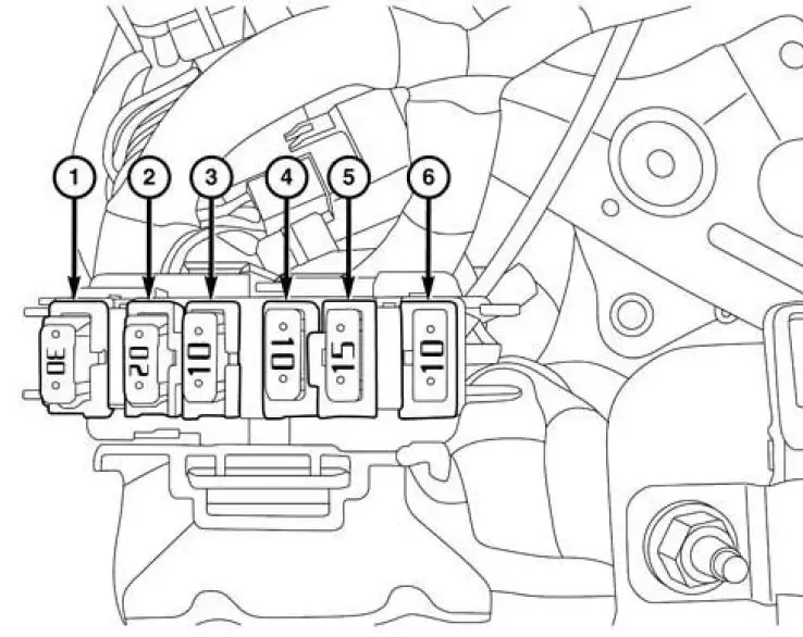
2014 Dodge Ram external power distribution box fuse Box diagram
1 Auxiliary Switch Bank Module (ASBM), HVAC and Integrated Center Stack (ICS)
2 Integrated Trailer Brake Module (ITBM)
3 Parktronics (PTS)
4 BCM and Cluster — Exterior Lighting Feeds
5 Spare
6 Radio with Built in Amplifier
Posted on by Rick Muscoplat