
2013 Charger Fuse Box Diagram: Exploring the Fuse Boxes
2013 Charger Fuse Box Diagram
In your 2013 Charger, you have two fuse boxes to monitor: the Front Power Distribution Center, also called the Integrated Power Module (IPM) under the hood and the Rear Power Distribution Center.
Let’s start with the one under the hood. Just pop the hood open and locate the Front Power Distribution Center on the passenger side of the engine compartment toward the front of the vehicle. It’s like the nerve center for your truck’s major systems—things like engine management, emissions, and ABS brakes are all controlled by the fuses in this box.
Now, for the second fuse box, pop the trunk and remove the spare tire cover and carpet. You’ll find the Rear Power Distribution Center to the right of the spare tire. Remove the cover to access the fuses. This one takes care of all the interior electrical stuff like the radio, power windows/locks, climate controls, and those handy courtesy lights. It’s essential to give both of these fuse boxes a once-over every so often to make sure none of the fuses are blown. If your electrical gadgets aren’t acting right, it might be a sign that something’s amiss with the fuses.
To learn more about automotive fuses, see this article
To learn how to check a fuse visually or without removing it, see this article
Find the most commonly replaced fuses here
The fuse box diagrams and tables below show all the fuses and all the relays. But most DIYers are looking for fuses and relays for the lights, power ports, and the blower motor. I’ve listed the most commonly checked/replaced fuses here to save time. Front Power Distribution Center=FPDC, Rear Power Distribution Center = RPDC
• Horn Fuse #11 20 FPDC
• Exterior Lights Fuses 6 & 7 40A RPDC
• Power Outlets Fuse #12 20A RPDC, Fuse #38 20A Inside Arm Rest 20A RPDC
• Blower Motor Fuse #15 40 RPDC
• Power Seats Fuse #31 25A RPDC
• Power Locks Fuse #9 30A RPDC
• Driver’s Window Fuse #10 30A RPDC
• Passenger Window Fuse #11 30A RPDC
A note about fuses, battery power and keep alive memory
The battery is stored under an access cover in the trunk. Remote battery terminals are located in the engine
compartment for jump-starting.
If you disconnect the battery or remove the PCM fuses from the fuse box, the PCM will lose its adaptive memory. In addition to losing adaptive memory, the PCM can also lose its baseline throttle body position and possibly the Steering Angle Sensor calibration.
You can avoid this by providing backup power using a jumper pack and an inexpensive OBDII cable. See this article for more information on providing backup power to prevent the loss of adaptive memory. Or, you can perform a throttle body relearn procedure and then drive the vehicle so it can relearn the new adaptive memory settings.
Here’s the procedure to perform a throttle body relearn after disconnecting the battery or the PCM fuse
1) Insert the ignition key and turn it to the “ON” position, but don’t start the engine.
2) Wait for all warning lights to go out. NOTE: The Check Engine Light may remain on.
3) Slowly depress the accelerator pedal all the way to the floor.
4) Slowly release the accelerator pedal until it’s all the way back up.
5) Turn the ignition key to “OFF”.
6) Start the engine.
Here’s the procedure to calibrate the steering angle sensor on a Dodge Vehicle
If your car battery becomes discharged, or you disconnect
Electronic Stability Control Warning Icon
the battery or the fuse to the stability control system, you may see the ESC warning light. Don’t panic, the system needs a quick recalibration.
1) Start the vehicle
2) Turn the steering wheel completely to the left and then to the right.
3) The “ESC Activation/Malfunction Indicator Light” should go out.
How to find your fuse and the devices served by that fuse
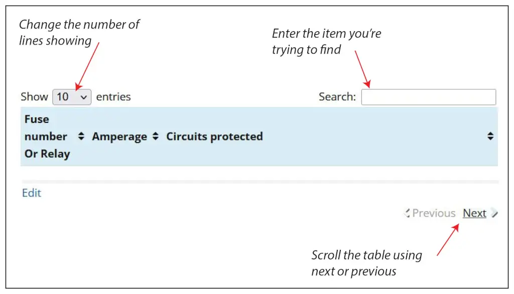
There are 42 fuse and relay slots in the Front Power Distribution Box. There are several ways to find the fuse you want in the chart below.
1) Enter a search term in the search box.
2) If you’d like to scroll all the fuses, change the number of entries to 100 in “Show Entries” box. Or, click NEXT at the bottom right of the table to scroll 10 items at a time.
2013 Charger fuse box diagram for front power distribution box
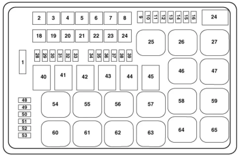
2013 Charger front power distribution box
| Fuse Number | Amperage | Circuits Protected |
|---|---|---|
| F1 | — | Spare |
| F2 | 40 | Radiator Fan #1 |
| F3 | 50 | Power Steering #1 |
| F4 | 30 | Starter |
| F5 | 40 | Anti-Lock Brakes |
| F6 | 25 | Anti-Lock Brakes |
| F7 | — | Spare |
| F8 | — | Spare |
| F9 | 20 | All-Wheel Drive Module – If Equipped |
| F10 | 10 | Security |
| F11 | 20 | Horns |
| F12 | 10 | Air Conditioning Clutch |
| F13 | — | Spare |
| F14 | — | Spare |
| F15 | 25 | Transmission |
| F16 | — | Spare |
| F18 | 50 | Radiator Fan #2 |
| F19 | 50 | Power Steering #2 |
| F20 | 30 | Wiper Motor |
| F21 | 30 | Headlamp Washers |
| F22 | — | Spare |
| F23 | — | Spare |
| F24 | — | Spare |
| F28 | 25 | Fuel Pump |
| F29 | 15 | Transmission Shifter |
| F30 | — | Spare |
| F31 | 25 | Engine Module |
| F32 | — | Spare |
| F33 | — | Spare |
| F34 | 25 | Powertrain #1 |
| F35 | 20 | Powertrain #2 |
| F36 | 10 | Anti-Lock Brake Module |
| F37 | 10 | Engine Controller/ Rad Fan Relays |
| F38 | 10 | Airbag Module |
| F39 | 10 | Power Steering Module/AC Clutch Relay |
| F48 | 10 | AWD Module/Front Axle Disconnect |
| F49 | — | Spare |
| F50 | — | Spare |
| F51 | 20 | Vacuum Pump |
| F52 | — | Spare |
| F53 | — | Spare |
2013 Charger fuse box diagram for the rear power distribution box
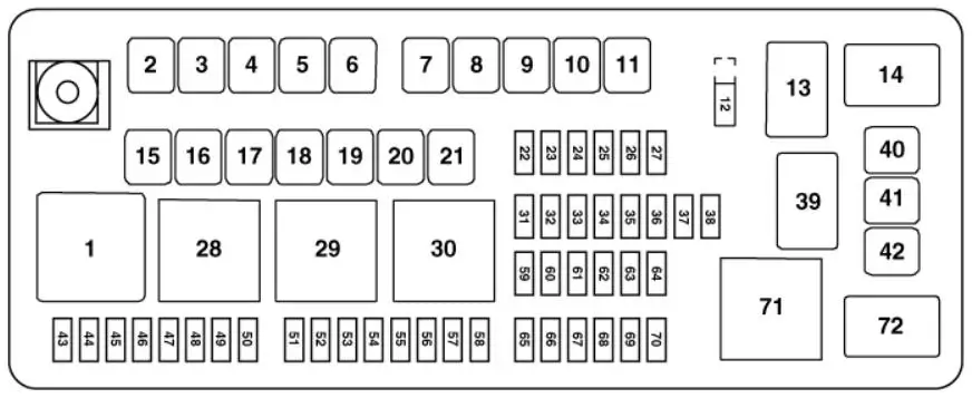
2013 charger rear power distribution box
| Fuse Number | Amperage | Circuits Protected |
|---|---|---|
| F1 | — | — |
| F2 | 60 | Front PDC Feed #1 |
| F3 | — | Spare |
| F4 | 60 | Front PDC Feed #2 |
| F5 | 30 | Sunroof |
| F6 | 40 | Exterior Lighting #1 |
| F7 | 40 | Exterior Lighting #2 |
| F8 | 30 | Interior Lighting/ Washer Pump |
| F9 | 30 | Power Locks |
| F10 | 30 | Driver Door |
| F11 | 30 | Passenger Door |
| F12 | 20 | Cigar Lighters, Instrument Panel & Power Outlet Console Rear |
| F15 | 40 | HVAC Blower |
| F16 | — | Spare |
| F17 | — | Spare |
| F18 | — | Spare |
| F19 | — | Spare |
| F20 | — | Spare |
| F21 | — | Spare |
| F22 | — | Spare |
| F23 | 10 | Fuel Door/Diagnostic Port |
| F24 | 15 | Radio Screen |
| F25 | 10 | Tire Pressure Monitor |
| F26 | — | Spare |
| F27 | 25 | Amplifier |
| F31 | 25 | Power Seats |
| F32 | 15 | HVAC Module/Cluster |
| F33 | 15 | Ignition Switch/Wireless Module |
| F34 | 10 | Steering Column Module/ Clock |
| F35 | 10 | Battery Sensor |
| F36 | — | Spare |
| F37 | 15 | Radio |
| F38 | 20 | Power Outlet Inside Arm Rest |
| F40 | — | Spare |
| F41 | — | Spare |
| F42 | 30 | Rear Defrost |
| F43 | 25 | Rear Heated Seats/Steering Wheel |
| F44 | 10 | Park Assist/Blind Spot/ Camera |
| F45 | 15 | Cluster/Rearview Mirror/Compass |
| F46 | 10 | Adaptive Cruise Control |
| F47 | 10 | Adaptive Front Lighting |
| F48 | 20 | Active Suspension |
| F49 | — | Spare |
| F50 | — | Spare |
| F51 | 20 | Front Heated Seats |
| F52 | 10 | Heated Cupholders/ Rear Heated Seat Switches |
| F53 | 10 | HVAC Module/In Car Temperature Sensor |
| F54 | — | Spare |
| F55 | — | Spare |
| F56 | — | Spare |
| F57 | — | Spare |
| F58 | 10 | Airbag Module |
| F59 | — | Spare |
| F60 | — | Spare |
| F61 | — | Spare |
| F62 | — | Spare |
| F63 | — | Spare |
| F64 | 25 | Rear Windows |
| F65 | 10 | Airbag Module |
| F66 | — | Spare |
| F67 | 15 | Run Sense |
| F68 | 15 | Illumination/ Rear Sunshade |
| F69 | — | Spare |
| F70 | — | Spare |
©, 2024 Rick Muscoplat