
2015 Taurus Fuse Box Diagram
2015 Taurus Fuse Box Diagram: Exploring the Fuse Boxes
In your 2015 Taurus, you’ve got two fuse boxes to keep track of: the Battery Junction Box, which is also called the Power Distribution Box under the hood, and the Body Control Module (BCM)/Passenger Compartment Fuse Panel.
Let’s start with the one under the hood. Just pop it open and take a look at the driver’s side of the engine compartment. You’ll find the power distribution box there next to the fender. It’s like the nerve center for your truck’s major systems—things like engine management, emissions, and ABS brakes are all controlled by the fuses in this box.
Now, for the second fuse box, The passenger compartment fuse box is located on the driver’s side of the vehicle under the dash and to the left of the steering wheel. Remove the panel cover to access the fuse cover.
This fuse box takes care of all the interior electrical stuff like the radio, power windows/locks, climate controls, and those handy courtesy lights. It’s essential to give both of these fuse boxes a once-over every so often to make sure none of the fuses are blown. If your electrical gadgets aren’t acting right, it might be a sign that something’s amiss with the fuses.
To learn more about automotive fuses, see this article
To learn how to check a fuse visually or without removing it, see this article
Find the most commonly replaced fuses here
The fuse box diagram and table below show all 62 fuses and all the relays. But most DIYers are looking for fuses and relays for the lights, power ports, and the blower motor. I’ve listed the most commonly checked/replaced fuses here to save time. I’ve also listed the most commonly replaced bulbs. A blown fuse or bulb are the two most common reasons for lighting issues.
Smart Junction Box/Passenger Compartment Fuse Box= SJB, Battery Junction Box/Power Distribution Box under the hood=PDB
• Blower Motor Fuse #18 40A PDB
• Right Turn Lamps Fuse #13 15A SJB
• Left Turn Lamps Fuse #14 15A SJB
• Stop lamp, Backup lamp Fuse #15 15A SJB
• Headlight HID Driver’s Side Fuse #57 20A PDB
• Headlight HID Passenger Side Fuse #78 20A PDB
• Headlight Low Beam Passenger Fuse #16 10A SJB
• Headlight Low Beam Driver Fuse #17 10A SJB
• Headlights High Beam Fuse #39 15A SJB
• Front Parking Lamps Fuse #30 15A SJB
• Rear Parking Lamps Fuse #40 10A SJB
• Horn Fuse #22 20A SJB
Click here for 2015 Ford Taurus Firing Order, spark plug gap and torque, fluid capacities
2015 Taurus Fuse Box Diagram for Battery Junction Box

2015 Taurus Fuse Box Diagram for the Power Distribution Box
How to find your fuse and the devices served by that fuse
There are 47 fuse and relay slots in the Battery Junction Box. There are several ways to find the fuse you want in the chart below.
1) Enter a search term in the search box.
2) If you’d like to scroll all the fuses, change the number of entries to 100 in “Show Entries” box. Or, click NEXT at the bottom right of the table to scroll 10 items at a time.
| Fuse Number | Amperage | Circuits Protected |
|---|---|---|
| F1 | — | Not used |
| F2 | — | Not used |
| F3 | — | Not used |
| F4 | 30 | Wiper motor relay |
| F5 | 50 | Anti-lock brake system pump |
| F6 | — | Not used |
| F7 | — | Not used |
| F8 | 20 | Moonroof, Power sunshade |
| F9 | 20 | Second row powerpoint |
| F10 | — | Not used |
| F11 | Relay | Heated rear window relay |
| F12 | — | Not used |
| F13 | Relay | Starter motor high-current relay |
| F14 | Relay | Left-hand cooling fan #2 relay |
| F15 | Relay | Fuel pump ultra relay |
| F16 | Relay | Not used |
| F17 | Relay | Not used |
| F18 | 40 | Front blower motor relay |
| F19 | 30 | Starter relay |
| F20 | 20 | Storage bin powerpoint |
| F21 | 20 | Rear heated seat module |
| F22 | Relay | Massage control seats relay |
| F23 | 30 | Driver power seat, Memory module |
| F24 | — | Not used |
| F25 | — | Not used |
| F26 | 40 | Rear window defrost relay |
| F27 | 20 | Cigar lighter |
| F28 | 30 | Climate controlled seats |
| F29 | 40 | Electric fan relay 1 |
| F30 | 40 | Electric fan relay 2 |
| F31 | 25 | Electric fan relay 3 |
| F32 | Relay | Power seat relay |
| F33 | Relay | Right-hand cooling fan relay |
| F34 | Relay | Blower motor high-current relay |
| F35 | Relay | Left-hand cooling fan #1 rel |
| F36 | — | Not used |
| F37 | — | Not used |
| F38 | — | Not used |
| F39 | — | Not used |
| F40 | — | Not used |
| F41 | — | Not used |
| F42 | 30 | Passenger power seat |
| F43 | 20 | Anti-lock brake system valves |
| F44 | — | Not used |
| F45 | 5 | Rain sensor |
| F46 | — | Not used |
| F47 | — | Not used |
| F48 | — | Not used |
| F49 | — | Not used |
| F50 | 15 | Heated mirrors |
| F51 | — | Not used |
| F52 | — | Not used |
| F53 | — | Not used |
| F54 | — | Not used |
| F55 | Relay | Wiper relay |
| F56 | — | Not used |
| F57 | 20 | Left high-intensity discharge headlamp |
| F58 | 10 | Alternator A-line |
| F59 | 10 | Brake on/off switch |
| F60 | — | Not used |
| F61 | — | Not used |
| F62 | 10 | A/C clutch relay |
| F63 | — | Not used |
| F64 | 15 | Massage control seats |
| F65 | 30 | Fuel pump relay, Fuel injectors |
| F66 | Relay | Powertrain control module relay |
| F67 | 20 | Oxygen sensor heater, Mass airflow sensor, Variable camshaft timing solenoid valve, Canister vent solenoid, Canister purge solenoid |
| F68 | 20 | Ignition coils |
| F69 | 20 | Vehicle power #1 (powertrain control module) |
| F70 | 15 | A/C clutch, Fan control relay coils (1-3), Variable air conditioning compressor, Auxiliary transmission warmup, Turbo charge waste-gate control, Electronic compressor bypass valve, All-wheel drive module, Positive crankcase ventilation heater |
| F71 | — | Not used |
| F72 | — | Not used |
| F73 | — | Not used |
| F74 | — | Not used |
| F75 | — | Not used |
| F76 | — | Not used |
| F77 | — | Not used |
| F78 | 20 | Right high-intensity discharge headlamp |
| F79 | — | Not used |
| F80 | — | Not used |
| F81 | — | Not used |
| F82 | — | Not used |
| F83 | — | Not used |
| F84 | — | Not used |
| F85 | — | Not used |
| F86 | 7.5 | Powertrain control module keep-alive power and relay, Canister vent solenoid |
| F87 | 5 | Run/start relay |
| F88 | Relay | Run/start relay |
| F89 | 5 | Front blower relay coil, Electrical power assist steering module |
| F90 | 10 | Powertrain control module run/start |
| F91 | 10 | Adaptive cruise control module |
| F92 | 10 | Anti-lock brake system module, Adaptive headlamp module |
| F93 | 5 | Rear window defroster relay |
| F94 | 30 | Passenger compartment fuse panel run/start |
| F95 | — | Not used |
| F96 | — | Not used |
| F97 | — | Not used |
| F98 | Relay | A/C clutch relay |
A note about fuses, battery power and keep alive memory
If you disconnect the battery or remove the PCM fuses from the fuse box, the PCM will lose its adaptive memory and baseline throttle body position. You can avoid this by providing backup power using a jumper pack and an inexpensive OBDII cable. See this article for more information on providing backup power to prevent the loss of adaptive memory. Or, you can perform a throttle body relearn procedure and then drive the vehicle so it can relearn the new adaptive memory settings. See this article for instructions on how to perform a 2014 F150 throttle body relearn procedure.
2015 Taurus Fuse Box Diagram for Body Control Module
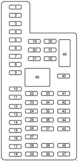
| Fuse Number | Amperage | Circuits Protected |
|---|---|---|
| F1 | 30 | Left front and right rear smart window motors |
| F2 | 15 | Driver seat switch power |
| F3 | 30 | Right front smart window motor |
| F4 | 10 | Demand lamps battery saver relay and coil |
| F5 | 20 | Audio amplifiers |
| F6 | 5 | Not used (spare) |
| F7 | 7.5 | Driver seat module logic, Left front door zone module, Keypad |
| F8 | 10 | Not used (spare) |
| F9 | 10 | SYNC module, Multi-function displays, Electronic finish panel, Radio frequency transceiver module |
| F10 | 10 | Run accessory relay |
| F11 | 10 | Intelligent access module logic, Heads-up display |
| F12 | 15 | Puddle lamp, Backlighting LED, Interior lighting |
| F13 | 15 | Right front turn, Right rear turn |
| F14 | 15 | Left front turn, Left rear turn |
| F15 | 15 | Stop lamp, Backup lamp |
| F16 | 10 | Right front low beam |
| F17 | 10 | Left front low beam |
| F18 | 10 | Start button, Keypad illumination, Brake shift interlock, Powertrain control module wakeup, Immobilizer transceiver module |
| F19 | 20 | Audio amplifier |
| F20 | 20 | All lock motor relay, Driver lock motor relay |
| F21 | 10 | Not used (spare) |
| F22 | 20 | Horn relay |
| F23 | 15 | Steering wheel control module logic, Instrument cluster |
| F24 | 15 | Steering wheel control module, Datalink |
| F25 | 15 | Decklid release relay |
| F26 | 5 | Ignition switch or push button start switch |
| F27 | 20 | Intelligent access module power |
| F28 | 15 | Not used (spare) |
| F29 | 20 | Radio, Global positioning system module |
| F30 | 15 | Front park lamps |
| F31 | 5 | Not used (spare) |
| F32 | 15 | Smart window motors, Master window and mirror switch, Rear window power sunshade module, Lock switch illumination |
| F33 | 10 | Not used (spare) |
| F34 | 10 | Reverse park aid module, Automatic high beam and lane departure module, Rear heated seat module, Blind spot monitor module, Rear video camera |
| F35 | 5 | Motorized humidity sensor, Heads-up display, Traction control switch |
| F36 | 10 | Heated steering wheel |
| F37 | 10 | Not used (spare) |
| F38 | 10 | Auto–dimming mirror (without automatic high beam and lane departure module), Moonroof module and switch |
| F39 | 15 | High beams |
| F40 | 10 | Rear park lamps |
| F41 | 7.5 | Occupant classification sensor, Restraint control module |
| F42 | 5 | Not used (spare) |
| F43 | 10 | Not used (spare) |
| F44 | 10 | Not used (spare) |
| F45 | 5 | Not used (spare) |
| F46 | 10 | Climate control module |
| F47 | 15 | Fog lamp relay |
| F48 | 30A Circuit Breaker | Front passenger power window, Rear power windows |
Tips to diagnose electrical issues on your 2006 Explorer
If your blower motor doesn’t work
The blower motor gets its power from the blower motor relay and Fuse #18 40A in the power distribution box.
If the circuit you’re working on contains a relay
• A simple way to test a relay is to swap in a similarly shaped relay and see if the component works.
• If that doesn’t work, remove the relay and test for power to the relay control coil and contacts using a multimeter. For more information on relay testing, see this article.
©, 2018 Rick Muscoplat