
2018 Edge Fuse Box Diagram
2018 Edge Fuse Box Diagram: Exploring the Fuse Boxes
The 2012 Edge has three fuse boxes; an underhood fuse box, a passenger compartment fuse box, and a high current fuse box. The passenger compartment fuse box is also called the Body Control Module (BCM). This post shows the 2018 Edge fuse box diagram for both boxes, and the circuits covered for each fuse
To learn more about automotive fuses, see this article
To learn how to check a fuse visually or without removing it, see this article
Find the most commonly replaced fuses here
The fuse box diagram and table below show all 62 fuses and all the relays. But most DIYers are looking for fuses and relays for the lights, power ports, and the blower motor. I’ve listed the most commonly checked/replaced fuses here to save time. I’ve also listed the most commonly replaced bulbs. A blown fuse or bulb are the two most common reasons for lighting issues.
SJB= Smart Junction Box/Passenger Compartment Fuse Box. PDB=Power Distribution Box
• Backup Light: Fuse #62 50A PCFB
• Blower Motor: Fuse #79 40A PDB
• Headlight HID Passenger Side: Fuse #18 20A PDB
• Headlight HID Driver’s Side: Fuse #44 20A PDB
• Horn: Fuse #50 20A PDB
• Power Ports: Back of console Fuse #5 20A PDB, Driver Front Fuse #10 20A PDB, Console Bin Fuse #16 20A PDB, Luggage compartment Fuse #17 20A PDB
• Stop/Turn/Brake: Body Control Module
• Parking lamps: Body Control Module
Power Windows: Driver’s Door Module Fuse #25 30A PCFB, Passenger Door Module Fuse #26 30A PCFB. Rear Windows 30A circuit breaker PCFB and Fuse#23 10A PCFB
A note about fuses, battery power and keep alive memory
If you disconnect the battery or remove the PCM fuses from the fuse box, the PCM will lose its adaptive memory and baseline throttle body position. You can avoid this by providing backup power using a jumper pack and an inexpensive OBDII cable. See this article for more information on providing backup power to prevent the loss of adaptive memory. Or, you can perform a throttle body relearn procedure and then drive the vehicle so it can relearn the new adaptive memory settings. See this article for instructions on how to perform a 2018 Edge throttle body relearn procedure.
2018 Edge Fuse Box Diagram for the Battery Junction Box

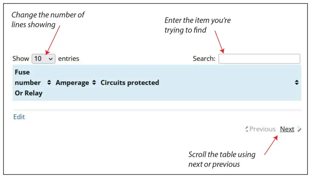
How to find your fuse and the devices served by that fuse
There are 87 fuse/relay slots in the Battery Junction Box. The chart shows only 10 to speed up load time. Here’s how to find the fuse and circuit you want.
1) Change the number of entries showing (in the Show Entries Box) to 100 and scroll the list.
2) Enter the name of the component you’re searching for in the Search box.
3) Use the Next/Previous buttons at the bottom of the table
PJB= Passenger Junction Box
HEGO = Heated Exhaust Gas Oxygen Sensor
VMV= Vapor Mangement Valve
PTEC= Powertrain Electronic Control Module (PCM)
CMS= Central Security Module
BSM= Body Security Module
CHMSL= Center High Mounted Stop Light
| Fuse number | Amperage | Circuits protected |
|---|---|---|
| F1 | 50 | BATT 2 (Smart Junction Box |
| F2 | 50 | BATT 3 (Smart Junction Box |
| F3 | 50 | BATT 1 (Smart Junction Box |
| F4 | 30 | Fuel pump, Injectors |
| F5 | 30 | Third row seat (left) |
| F6 | 40 | ABS pump |
| F7 | 40 | Powertrain Control Module (PCM) |
| F8 | 40 | Heated windshield (left) |
| F9 | 40 | Heated windshield (right) |
| F10 | 30 | Power seat (right) |
| F11 | 30 | Starter |
| F12 | 30 | Third row seat (right) |
| F13 | 30 | Trailer tow battery charger |
| F14 | 30/40 | Memory seats (DSM)/Non-memory seats |
| F15 | 40 | Rear defrost, Heated mirrors |
| F16 | 40 | Blower motor |
| F17 | 30 | Trailer electronic brakes |
| F18 | 30 | Auxiliary blower motor |
| F19 | 30 | Running boards |
| F20 | — | Not used |
| F21 | 20 | Rear power point |
| F22 | 20 | Subwoofer |
| F23 | 20 | 4x4 |
| F24 | 10 | Powertrain Control Module (PCM) KAP, CAN vent |
| F25 | 20 | Front power point/Cigar lighter |
| F26 | 20 | 4x4 module |
| F27 | 20 | 6R Transmission module |
| F28 | 20 | Heated seats |
| F29 | 20 | Headlamps (right) |
| F30 | 25 | Rear wiper |
| F31 | 15 | Fog lamps |
| F32 | 5 | Power mirrors |
| F33 | 30 | ABS valve |
| F34 | 20 | Headlamps (left) |
| F35 | 10 | AC clutch |
| F36 | — | Not used |
| F37 | 30 | Front wiper |
| F38 | 15 | 5R Transmission |
| F39 | 15 | PCM power |
| F40 | 15 | Fan clutch, PCV valve, AC clutch relay, GCC fan |
| F41 | 15 | SDARS/DVD |
| F42 | 15 | Redundant brake switch, EVMV, MAFS, HEGO, EVR, VCT1, VCT2, CMCV, CMS |
| F43 | 15 | Coil on plug (4.6L engine only), Coil tower (4.0L engine only) |
| F44 | 15 | Injectors |
| F45A | — | Not used |
| F45B | Relay | GCC fan relay |
| F46A | — | Not used |
| F46B | — | Not used |
| F49 | Relay | Fuel pump relay |
| F50A | Relay | Fog lamps relay |
| F50B | Relay | AC clutch relay |
| F51 | — | Not used |
| F52 | — | A/C clutch (diode) |
| F53 | — | Not used |
| F54 | Relay | Trailer battery charger relay |
| F55A | Relay | PCM relay |
| F55B | Relay | Front wiper relay |
| F56A | Relay | Blower relay |
| F56B | Relay | Starter relay |
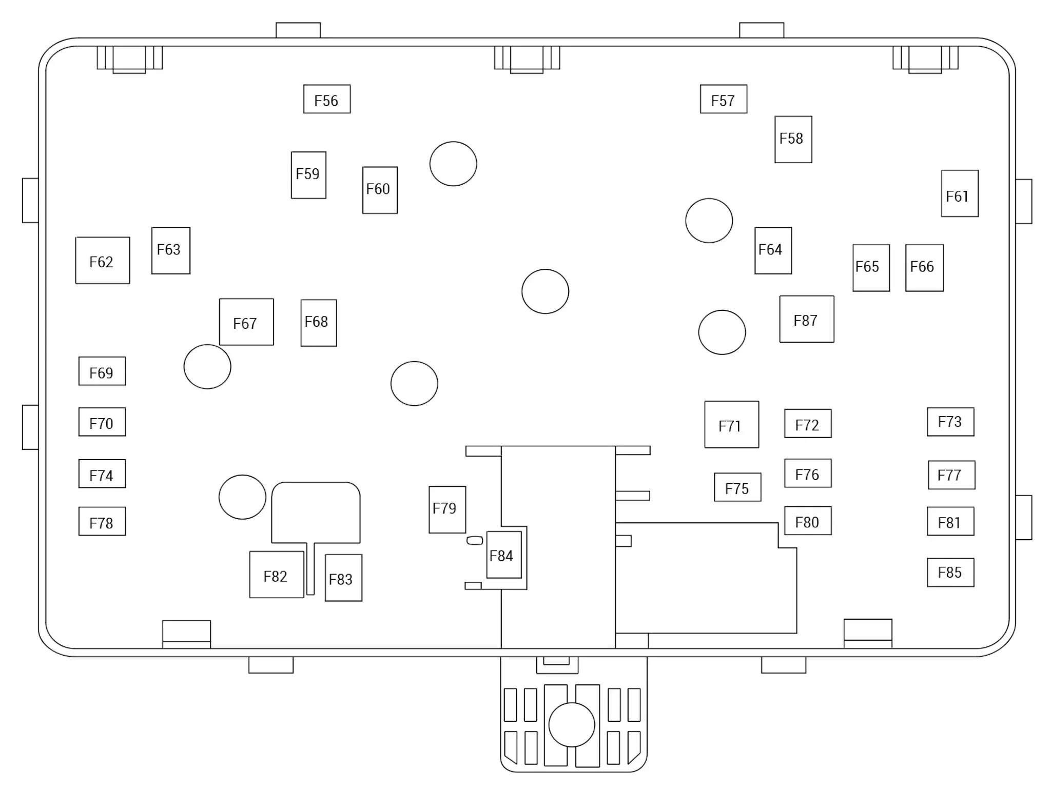
Explorer Fuse Box Diagram for Cabin/Passenger Compartment Fuse Panel
The cabin fuse panel is located on the far left-hand side of the instrument panel. Ford refers to this as the passenger compartment fuse box or the smart junction box (SJB).
| Fuse Number | Amperage | Circuits Protected |
|---|---|---|
| F1 | 30 | Not used |
| F2 | — | Starter relay |
| F3 | 15 | Rain sensor module, Rear window wiper motor |
| F4 | — | Blower motor relay. |
| F5 | 20 | Power point 3 - back of console |
| F6 | — | Not used |
| F7 | 20 | Powertrain Control Module (PCM) |
| F8 | 20 | Evaporative emission (EVAP) canister vent valve Evaporative emission (EVAP), vapor blocking valve, Evaporative emission (EVAP) purge valve Variable camshaft timing solenoids, Heated oxygen sensors |
| F9 | — | Powertrain control module relay |
| F10 | 20 | Front power outlet socket |
| F11 | 15 | Coil On Plugs (COPs) |
| F12 | 15 | Power transfer unit (PTU), Active grille shutter, Cabin heater coolant pump, Air Conditioning (A/C) compressor control solenoid Turbocharger Bypass (TCBY) valve, Turbocharger Wastegate Regulating, Valve Solenoid (TCWRVS), Oil pressure control solenoid, Power transfer unit (PTU) auxiliary pump, Transmission fluid heater coolant control valve, Vacuum solenoid valve (VSV) |
| F13 | — | Not used |
| F14 | — | Not used |
| F15 | 20 | Front power outlet socket 2 |
| F16 | 20 | Power point 2 - console bin. |
| F17 | 20 | Power point 4 - luggage compartment |
| F18 | 20 | RH HID headlamp |
| F19 | 10 | Run-start electronic power assist steering |
| F20 | 10 | Run/start lighting |
| F21 | 15 | Transmission oil pump logic power (start/stop |
| F22 | 10 | Air conditioner clutch solenoid. |
| F23 | 15 | Run-start 6 Blind spot information system. Rear view camera. Adaptive cruise control. Heads-up display. Voltage quality module (start/stop). Front split view camera. Front split view camera module. |
| F24 | 10 | Not used (spare) |
| F25 | 10 | Run-start anti-lock brake system |
| F26 | 10 | Run-start powertrain control module |
| F27 | — | Not used |
| F28 | 10 | Rear washer pump |
| F29 | — | Not used |
| F30 | — | Not used |
| F31 | — | Not used |
| F32 | — | Electronic fan 1 relay |
| F33 | — | A/C clutch relay |
| F34 | 15 | Not used (spare) |
| F35 | — | Not used |
| F36 | — | Not used |
| F37 | 10 | Power transfer unit fan |
| F38 | — | Electronic fan 2 relay |
| F39 | — | Electric fan 3 relay |
| F40 | — | Horn relay |
| F41 | — | Not used |
| F42 | — | Fuel pump relay |
| F43 | 10 | 2nd row easy fold seat release |
| F44 | 20 | LH HID headlamp |
| F45 | — | Not used |
| F46 | — | Not used |
| F47 | — | Not used |
| F48 | 15 | Not used (spare). |
| F49 | — | Not used |
| F50 | 20 | Horn |
| F51 | — | Not used |
| F52 | — | Not used |
| F53 | — | Not used |
| F54 | 10 | Brake on off switch |
| F55 | 10 | ALT sensor |
| F56 | — | Not used |
| F57 | — | Not used |
| F58 | 30 | Fuel pump feed. Port fuel injectors (3.5L). |
| F59 | 40 | Electronic fan 3 |
| F60 | 40 | Electronic fan 1. |
| F61 | — | Not used |
| F62 | 50 | Body control module 1 |
| F63 | 25 | Electronic fan 2 |
| F64 | — | Not used |
| F65 | 20 | Front heated seat |
| F66 | 15 | Heated wiper park |
| F67 | 50 | Body control module 2. |
| F68 | 40 | Heated rear window |
| F69 | 30 | Anti-lock brake system valves |
| F70 | 30 | Passenger seat |
| F71 | — | Not used |
| F72 | 20 | Transmission oil pump (start/stop). |
| F73 | 20 | Rear heated seats |
| F74 | 30 | Driver seat module. Power driver seat (less memory). |
| F75 | 25 | Wiper motor 1. |
| F76 | 30 | Power liftgate module |
| F77 | 30 | Climate control seat module |
| F78 | 40 | Trailer lighting module |
| F79 | 40 | Blower motor |
| F80 | 25 | Wiper motor 2 |
| F81 | 40 | 110 volt inverter. |
| F82 | — | Not used |
| F83 | 20 | Not used (spare) |
| F84 | 30 | Starter solenoid |
| F85 | — | Not used |
| F86 | 60 | Anti-lock brake system pump |
2018 Edge Fuse Box Diagram High Current Battery Junction Box

F1 – Not used
F2 125 Body Control Module (BCM)
F3 50 Low voltage Direct Current/Direct Current (DC/DC) converter
F4 60 Battery Junction Box (BJB)
F5 – Not used
F6 – Not used
F7 275 Generator
F8 80 Power Steering Control Module (PSCM)
Tips to diagnose electrical issues on your 2018 Edge
Headlight operation
Unlike in older models, the multifunction headlight switch does not switch power to the headlights. It is simply a request for headlights. The multifunction switch has a series of resistors that drop voltage as you turn the stalk. The Body Control Module determines whether you’re requesting parking lights, headlights, or high-beam lights based on the voltage drop. The actual power switching of power from the headlight fuse to the headlights is done inside the smart junction box.
If your headlights aren’t working, the easiest way to diagnose the problem is to use a bidirectional scan too to view live data from the smart junction box. You will see that on the scan tool if it’s receiving the headlights ON request. However, if you’ve turned the stalk to headlights and the smart junction box isn’t seeing the request, then the problem is in the multifunction switch or the wiring from the MF switch to the SHB
If your power windows don’t work
• The front power windows are controlled by a door module in each of the front doors. Each door module has its own fuse in the PCFB (Body Control Module). The rear windows are powered by a 30A circuit breaker in the PCFB
If your blower motor doesn’t work
The blower motor gets its power from the blower motor relay #79 in the battery junction/power distribution box.
If the circuit you’re working on contains a relay
• A simple way to test a relay is to swap in a similarly shaped relay and see if the component works.
• If that doesn’t work, remove the relay and test for power to the relay control coil and contacts using a multimeter. For more information on relay testing, see this article.
©, 2018 Rick Muscoplat