
2018 F150 Fuse Box Diagram: Exploring the Fuse Boxes
2018 F150 Fuse Box Diagram: Find the correct fuse for the circuit you’re working on
This article includes 2018 F150 Fuse Diagrams and a full listing of all the fuses and relays in your vehicle. In your 2018 Ford F150, you’ve got two fuse boxes to keep track of: the Battery Junction Box, which is also called the Power Distribution Box under the hood, and the Body Control Module (BCM)/Passenger Compartment Fuse Panel.
Let’s start with the one under the hood. Just pop the hood and take a look near the firewall on the passenger side of the engine compartment. You’ll find the power distribution box there. It’s like the nerve center for your truck’s major systems—things like engine management, emissions, and ABS brakes are all controlled by the fuses in this box.
Now, for the second fuse box, crawl under the dash on the driver’s side. It’s tucked away in the footwell. This one takes care of all the interior electrical stuff like the radio, power windows/locks, climate controls, and those handy courtesy lights. It’s essential to give both of these fuse boxes a once-over every so often to make sure none of the fuses are blown. If your electrical gadgets aren’t acting right, it might be a sign that something’s amiss with the fuses.
To learn more about automotive fuses, see this article
To learn how to check a fuse visually or without removing it, see this article.
Find the most commonly replaced fuses here
The fuse box diagram and table below show all 62 fuses and all the relays. But most DIYers are looking for fuses and relays for the lights, power ports, and the blower motor. I’ve listed the most commonly checked/replaced fuses here to save time. I’ve also listed the most commonly replaced bulbs. A blown fuse or bulb are the two most common reasons for lighting issues.
BCM = Body Control Module under the dash. BJB = Battery Junction Box under the hood
• The parking, stop, turn, backup, headlights, etc. are all powered through the body control module. There are no individual fuses for each light.
• Blower Motor: Fuse #20 40A (BJB)
• Horn: Fuse #1 20A (BJB)
• Power Ports: Cigar lighter power point 1 Fuse #6 20 (BJB), Power point 2 Fuse #8 20A (BJB), Power Point 3 Fuse #51 20A (BJB), USB Smart Charger Fuse #58 5, Power Point #4 Fuse #92 20A (BJB).
2018 F150 Fuse Box Diagram for the battery junction box
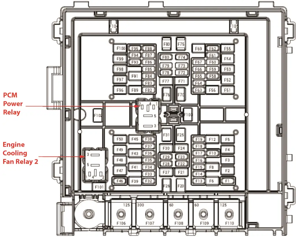
2018 F150 battery junction box
How to find your fuse and the devices served by that fuse
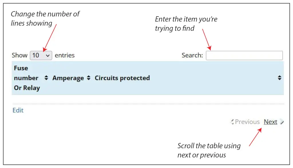
There are 110 fuse slots in the Battery Junction Box. The chart shows only 10 to speed up load time. Here’s how to find the fuse and circuit you want.
1) Change the number of entries showing (in the Show Entries Box) to 100 and scroll the list.
2) Enter the name of the component you’re searching for in the Search box.
3) Use the Next/Previous buttons at the bottom of the table
| Fuse number | Amperage | Circuits protected |
|---|---|---|
| F1 | 25 | Horn |
| F2 | 50 | Cooling Fan Motor 1, Aux Cooling Fan Motor |
| F3 | 30 | Windshield wiper motor |
| F4 | 60 | Body Control Module (BCM) |
| F5 | 30 | Starter motor |
| F6 | 20 | Instrument panel power point 1 |
| F7 | — | Not used |
| F8 | 20 | Instrument panel power point 2 |
| F9 | 30 | Fuel pump relay |
| F10 | 5 | Rain sensor |
| F11 | — | Not used |
| F12 | 15 | Upfitter 1 |
| F13 | 10 | Transmission relay, Transfer Case Control Module (TCCM), Cruise Control Module (CCM), Rear window Defrost Relay |
| — | Not used | |
| F15 | 7.5 | Direct Current/Direct Current (DC/DC) Converter Control Module, Front Parking aid camera, Headlamp assembly LH, Headlamp assembly RH |
| F15 | 15 | Direct Current/Direct Current (DC/DC) Converter Control Module, Front Parking aid camera, Headlamp assembly LH, Headlamp assembly RH, Phantom Raptor |
| F16 | 10 | Transmission Control Module (TCM), Powertrain control module (PCM) |
| F17 | 10 | Anti-lock Brake System (ABS) module |
| F18 | 10 | Power Steering Control Module (PSCM) |
| F19 | 5 | Upfitter 5 |
| F20 | 40 | Blower motor control module |
| F21 | 30 | Front seat control switch RH |
| F22 | 20 | Subwoofer amplifier, Audio Signal Processing (DSP) Module |
| F23 | 10 | Generator |
| F24 | 30 | Trailer Brake Control (TBM) Module |
| F25 | 50 | Body Control Module (BCM) |
| F26 | 50 | Cooling Fan Motor 2 |
| F27 | 30 | Front seat control switch LH, Driver front seat module (DSM) |
| F28 | 15 | Front Controls interface Module (FCIM) |
| F29 | 15 | Integrated Wheel End (IWE) solenoid |
| F30 | 25 | Trailer Module (TRM) |
| F31 | — | Not used |
| F32 | 10 | Air conditioning (AC) clutch and AC field coil |
| F33 | — | Not used |
| F34 | 10 | Fuel rail pressure relief valve (FRPRV), Fuel volume control valve (FVCV) solenoid |
| F35 | 20 | Gasoline Ignition coil-on-plugs |
| F35 | 15 | Diesel Glow plug control module (GPCM), Mass airflow/intake air temperature (MAF/IAT) sensor, NOx #12 sensor module |
| F36 | 10 | Turbocharger Bypass (TCBY) Valve Oil pressure control solenoid Turbocharger Wastegate Regulating Valve Solenoid (TCWRVS) Transmission heater engine coolant control valve Vacuum Solenoid Valve (VSV) Upper active grille shutter actuator Lower active grille shutter actuator Crankcase ventilation heater Air Conditioning (A/C) compressor control solenoid Cabin heater coolant pump Engine cooling fan relays Aux cooling fan relay Charge Air Cooler (CAC) cooling fan relay A/C clutch relay |
| F37 | 25 | Heated Oxygen Sensors Gasoline Variable Camshaft Timing solenoid Evaporative Emission (EVAP) purge valve Evaporative Emission (EVAP) canister vent valve EVAP vapor blocking valve Intake Manifold Runner Control bank 1 (IMRC1) sensor 15 Reductant pump control module Diesel EGR Cooler Bypass Valve (EGRCBV) solenoid |
| F38 | 25 | Gasoline Powertrain Control Module (PCM) |
| F38 | 20 | Diesel Powertrain Control Module (PCM) |
| F39 | — | Not used |
| F40 | — | Not used |
| F41 | 30 | Direct Current/tDitieTciotifuirerent (DC/DC) |
| F42 | 30 | Transmission fluid pump |
| F43 | 20 | Trailer Module (TOM) |
| F44 | — | Not used |
| F45 | — | Not used |
| F46 | 10 | Steering column lock module |
| F47 | 50 | Electric booster heater |
| F48 | 30 | Water-in-fuel sensor |
| F49 | — | Not used |
| F50 | 30 | Fuel injectors, Fuel pump control module, Powertrain control module |
| F51 | 50 | Frear console power point, Seat power point |
| F52 | 50 | Electric booster heater |
| F53 | 25 | Trailer tow connector |
| F54 | — | Not used |
| F55 | 15 | Upfitter 2 |
| F56 | — | Not used |
| F57 | — | Not used |
| F58 | 5 | USB charge port |
| F59 | — | Not used |
| F60 | — | Not used |
| F61 | 15 | Headlamp assembly LH |
| F62 | 5 | Upfitter 6 |
| F63 | 25 | Transfer Case Control Module (TCCM) |
| F64 | 15 | Transfer Case Control Module (TCCM) |
| F65 | — | Not used |
| F66 | — | Not used |
| F67 | — | Not used |
| F68 | — | Not used |
| F69 | — | Not used |
| F70 | 40 | Anti-lock Brake System (ABS) module |
| F71 | 25 | Transfer Case Control Module (TCCM) |
| F72 | — | Not used |
| F73 | — | Not used |
| F74 | 10 | Trailer tow connector |
| F75 | — | Not used |
| F76 | 40 | Body Control Module (BCM) |
| F77 | 30 | Driver front Seat Module (DSM) |
| F78 | 10 | Spot lamp control module |
| F79 | — | Not used |
| F80 | 10 | Heated windshield element |
| F80 | 10 | Upfitter 4 |
| F81 | — | Not used |
| F82 | 30 | Transmission fluid auxiliary pump |
| F82 | 5 | Powertrain Control Module (PCM) |
| F83 | 15 | Transmission Control Module (TCM) |
| F84 | — | Not used |
| F85 | — | Not used |
| F86 | — | Not used |
| F87 | — | Not used |
| F88 | 10 | Driver multi-contour seat module |
| F88 | 10 | Upfitter 3 |
| F89 | 30 | Running Board control Module (RBM) |
| F90 | — | Not used |
| F91 | — | Not used |
| F92 | — | Not used |
| F93 | 15 | Exterior mirror LH, Exterior mirror RH |
| F94 | 15 | Heated rear seat module |
| F95 | 15 | Headlamp assembly RH 1 |
| F96 | — | Not used |
| F97 | 40 | Phantom/Raptor Charge Air Cooler (CAC), Cooling fan motor 1, Charge air cooler (CAC) Cooling fan motor 2 |
| F97 | 50 | Diesel Electric booster heater |
| F98 | 15 | Transmission fluid pump |
| F99 | 40 | Rear window defrost grid |
| F100 | 25 | Glow Plug Control Module (GPCM) |
| F101 | 25 | Cooling fan motor 2 |
| F102 | 30 | Rear sliding window motor |
| F103 | 20 | Trailer tow connector |
| F104 | 15 | Heated rear seat module |
| F105 | 10 | Exterior mirror LH, exterior Mirror RH |
| High Current Fuses | ||
| F106 | 125 | Power Steering Control Module (PSCM) |
| F107 | 300 | Generator |
| F108 | 60 | Anti-lock Brake System (ABS) module |
| F109 | 60 | Direct Current/Alternating Current (DC/AC) inverter |
| F110 | 60 | Glow Plug Control Module (GPCM) |
A note about fuses, battery power and keep alive memory
If you disconnect the battery or remove the PCM fuses from the fuse box, the PCM will lose its adaptive memory and baseline throttle body position. You can avoid this by providing backup power using a jumper pack and an inexpensive OBDII cable. See this article for more information on providing backup power to prevent the loss of adaptive memory. Or, you can perform a throttle body relearn procedure and then drive the vehicle so it can relearn the new adaptive memory settings. See this article for instructions on how to perform a 2017 F150 throttle body relearn procedure.
2018 F150 Fuse Box Diagram for the body control module/passenger compartment fuse box
A body control module (BCM) is an electronic control unit found in modern vehicles that manages various body-related functions and accessories. It acts as a centralized control system for components that aren’t directly related to the engine, transmission, or braking systems.
The body control module receives input signals from various switches, sensors, and user controls, and then sends output signals to activate or deactivate the corresponding components accordingly. It helps integrate and coordinate the operation of these convenience and safety features in the vehicle.
The BCM has 38 fuse slots, but the chart shows only 10 to speed up load time. Here’s how to find the fuse and circuit you want.
1) Change the number of entries showing (in the Show Entries Box) to 100 and scroll the list.
2) Enter the name of the component you’re searching for in the Search box.
3) Use the Next/Previous buttons at the bottom of the table
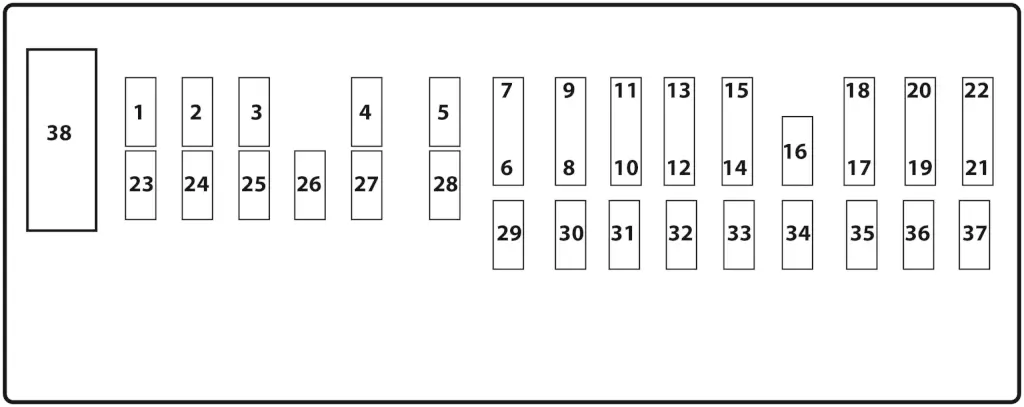
2018 F150 Passenger Compartment Fuse Box
| Fuse number | Amperage | Circuits protected |
|---|---|---|
| F1 | — | Not used |
| F2 | 7.5 | Front seat control switch LH |
| F3 | 20 | Front door latch LH |
| F4 | 5 | Trailer Brake Control (TBM) Module |
| F5 | — | Not used |
| F6 | — | Not used |
| F7 | — | Not used |
| F8 | 10 | Security horn relay |
| F9 | 10 | Battery Energy Control Module B (BECMB) |
| F10 | 5 | Telematics Control Unit (TCU) module |
| F11 | 5 | Intrusion sensor |
| F12 | 7.5 | Gateway Module A (GWM), Front controls interface module (FCIM) |
| F13 | 7.5 | Steering column control module {SCCM) |
| F14 | 10 | Brake Pedal Position (BPP) switch |
| F15 | 10 | Gateway Module A (GWM), Telematics module |
| F16 | 15 | Tailgate latch actuator |
| F17 | 5 | Head up display (HUD) module |
| F18 | 5 | Ignition switch |
| F19 | 7.5 | Battery Energy Control Module B (BECMB), Restraints control module (RCM) |
| F20 | 7.5 | Headlamp switch |
| F21 | 5 | In-vehicle temperature and humidity sensor, Head up (HUD) module |
| F22 | 5 | Occupant Classification System Module (OCSM) |
| F23 | 20 | Front door window control switch LH, Direct current/Alternating current (DC/AC) inverter, roof opening panel motor assemblies, power sliding rear window switch |
| F24 | 20 | Front door latch RH, Front door latch LH, Rear door latch LH, Rear door latch RH, Tailgate lock actuator |
| F25 | 30 | Driver Door Module (DDM) |
| F26 | 30 | Passenger Door Module (PDM) |
| F27 | 30 | Roof opening panel motor assemblies, Shield (Sunshade) motor |
| F28 | — | Not used |
| F29 | — | Not used |
| F30 | — | Not used |
| F31 | 15 | Adjustable pedal control switch |
| F32 | 10 | Sync module (APIM), Radio Transceiver Module (RTM), Front control/display interface module(FCDIM) |
| F33 | 20 | Audio front Control Module (ACM) |
| F34 | 30 | Ignition Relay |
| F35 | 5 | Column shifter, floor shifter, Auxiliary switches |
| F36 | 5 | Auto dimming interior mirror, Heated rear seat module, image processing module A (IPMA), image processing module B (IPMB), Heated steering wheel module (HSWM) |
| F37 | — | Not used |
| F38 | 30 | Rear door window control switch LH, rear door window control switch RH |
Tips to diagnose electrical issues on your 2017 F150
If your power windows don’t work
• In previous model years, Ford used a 30A circuit breaker to provide power to the windows. However, starting in the 2014 F150, they went back to using fuses for the front windows. In 2015, Ford switched to using Door Control Modules on the Driver and Passenger sides to operate the front windows.
The fuse for the driver’s side power window (Driver door control module) is #25 30A in the BCM, and the #26 30A for the passenger side window (Passenger Door control module. However, Ford still uses a 30A circuit breaker for the rear passenger and driver’s side windows and the power sliding rear window.
The circuit breaker for the rear windows is located in the BCM in slot 38.
If your blower motor doesn’t work
The blower motor gets its power from the blower motor relay #68 in the battery junction/power distribution box. The blower motor relay is powered by fuse #60 40A
If the circuit you’re working on contains a relay
• A simple way to test a relay is to swap in a similarly shaped relay and see if the component works.
• If that doesn’t work, remove the relay and test for power to the relay control coil and contacts using a multimeter. For more information on relay testing, see this article.
©, 2018 Rick Muscoplat