
2019 Escape Fuse Box Diagram: Exploring the Fuse Boxes
2019 Escape Fuse Box Diagram: Find the right fuse for the circuit you’re working on
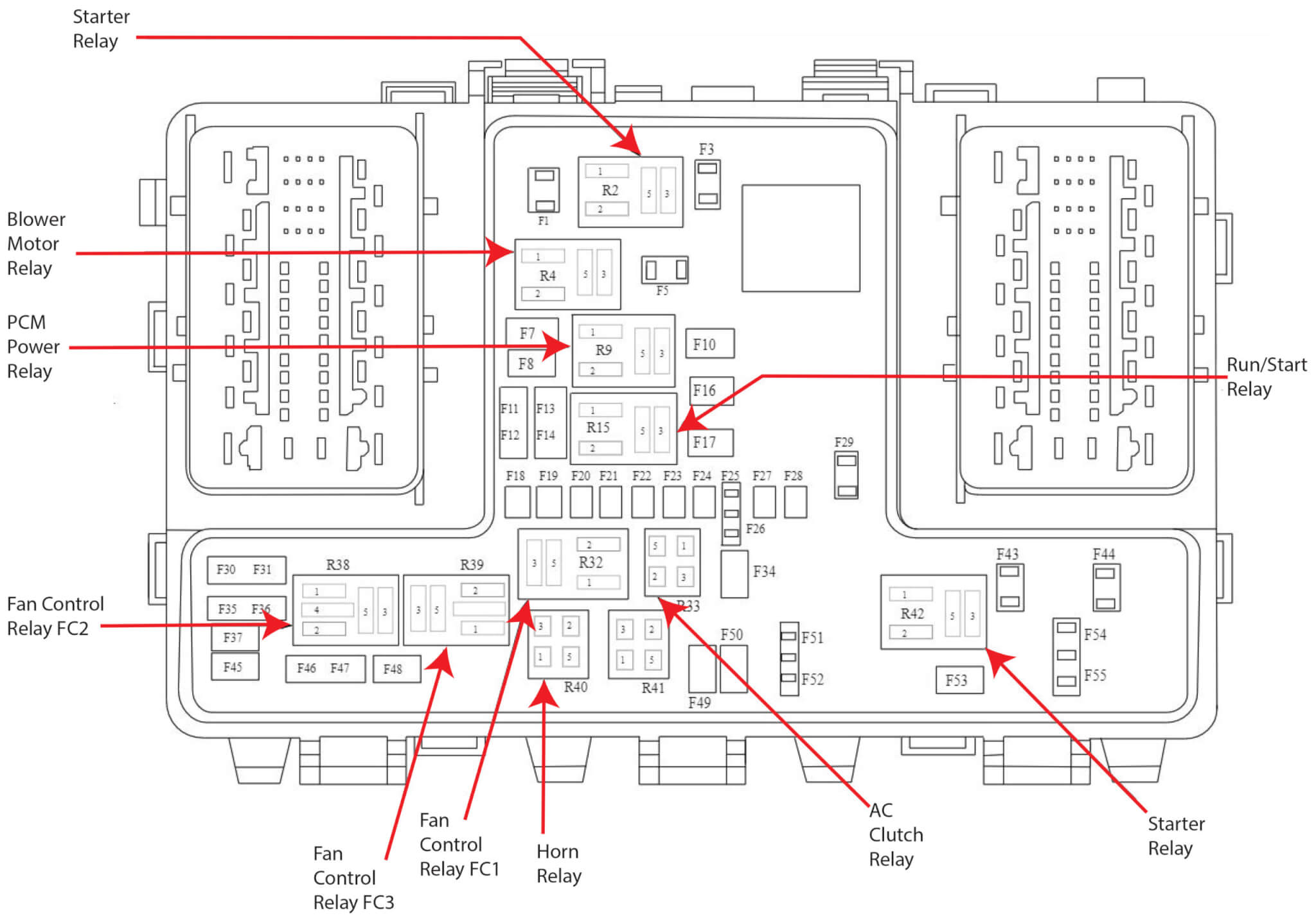
In your 2019 Escape, you’ve got three fuse boxes to keep track of: the Power Distribution Box under the hood, the Body Control Module (BCM)/Passenger Compartment Fuse Panel, and the Luggage Compartment fuse box.
Let’s start with the one under the hood. Just pop the hood and locate the power distribution box on the driver’s side of the engine compartment near the firewall. It’s like the nerve center for your truck’s major systems—things like engine management, emissions, and ABS brakes are all controlled by the fuses in this box.
Now, for the second fuse box, crawl under the dash on the passenger side. The passenger compartment fuse box is below the dash under the glove box. This one takes care of all the interior electrical stuff like the radio, power windows/locks, climate controls, and those handy courtesy lights.
The luggage compartment fuse box is in the luggage compartment behind the passenger side wheel well. Remove the fuse panel cover to gain access to the fuses.
It’s essential to give both of these fuse boxes a once-over every so often to make sure none of the fuses are blown. If your electrical gadgets aren’t acting right, it might be a sign that something’s amiss with the fuses.
To learn more about automotive fuses, see this article
To learn how to check a fuse visually or without removing it, see this article
Find the most commonly replaced fuses here
The fuse box diagram and table below show all the fuses and all the relays. But most DIYers are looking for fuses and relays for the lights, power ports, and the blower motor. I’ve listed the most commonly checked/replaced fuses here to save time. I’ve also listed the most commonly replaced bulbs. A blown fuse or bulb are the two most common reasons for lighting issues.
Power Distribution Box = PDB, Passenger Compartment Fuse Box = PCFB, Luggage Compartment Fuse Box = LCFB
• Blower Motor Fuse $10 40A PDC
• Front cigar lighter or power outlet Fuse #15 20A PDC, Center power outlet Fuse #18 20A PDC, Rear power outlet Fuse #26 20A Luggage compartment fuse box, Luggage compartment outlet Fuse #26 20A LCFB
• Horn Fuse #20 15A PDC
• Active grille shutters Fuse #36 5A PDC
• Headlamps Fuse #74 15A PCFB
• Backup lamps Fuse #75 10A PCFB
A note about fuses, battery power and keep alive memory
If you disconnect the battery or remove the PCM fuses from the fuse box, the PCM will lose its adaptive memory and baseline throttle body position. You can avoid this by providing backup power using a jumper pack and an inexpensive OBDII cable. See this article for more information on providing backup power to prevent the loss of adaptive memory. Or, you can perform a throttle body relearn procedure and then drive the vehicle so it can relearn the new adaptive memory settings. See this article for instructions on how to perform a 2019 Escape throttle body relearn procedure.
2019 Escape Fuse Box Diagram for the Battery Junction Box/Power Distribution Box
| Fuse Number | Amperage | Circuits Protected |
|---|---|---|
| F1 | — | Not used |
| F2 | — | Not used |
| F3 | — | Not used |
| F4 | — | Not used |
| F5 | — | Not used |
| F6 | — | Not used |
| F7 | 50 | Anti-lock Brake System (ABS) module |
| F8 | 30 | Anti-lock Brake System (ABS) module |
| F9 | 40/50 | Cooling fan (600 Watt)/Cooling fan (390 Watt). |
| F10 | 40 | Blower motor relay |
| F11 | 30 | Low voltage Direct Current/Direct Current (DC/DC) Converter |
| F12 | 30 | PCM power relay |
| F13 | 30 | Starter relay |
| F14 | 25 | Cooling fan (600 Watt) |
| F15 | 20 | Auxiliary power point |
| F16 | 25 | Front power window (without door control unit). |
| F17 | 40 | Cooling fan (600 Watt) |
| F18 | 20 | Center power outlet |
| F19 | 5 | Anti-lock brake system and electronic 5A stability program 15 feed |
| F20 | 15 | Horn |
| F21 | 5 | Stop light switch. |
| F22 | 15 | Battery monitor system |
| F23 | 5 | Relay coils |
| F24 | 5 | Light switch module |
| F25 | 10 | Occupant classification system |
| F26 | 25 | Oil pump |
| F27 | 15 | Air conditioner clutch |
| F28 | 10 | Vehicle power - fuel injector (2.5L engine). Blind spot information system and rear view camera (stop/start equipped vehicles) |
| F29 | — | Not used |
| F30 | 10 | Partially heated windshield |
| F31 | 5 | Powertrain control relay coil |
| F32 | 15/10 | Vehicle power (2.0L and 2.5L engine)/Vehicle power (1.5L engine) |
| F33 | 10/15 | Vehicle power 2 (2.0L and 2.5L engine)/Vehicle power 2 (1.5L engine) |
| F34 | 10 | Vehicle power 3 |
| F35 | 15/10 | Vehicle power 4 (2.0L and 2.5L engine)/Vehicle power 4 (1.5L engine) |
| F36 | 5 | Active grille shutters |
| F37 | 10 | Passenger airbag deactivation indicator |
| F38 | 5 | Engine control module and transmission 5A control module ignition feed |
| F39 | 20 | Heated driver seat |
| F40 | 5 | Electronic power assist steering 15 feed |
| F41 | 20 | Body control module 15 feed |
| F42 | 15 | Rear wiper |
| F43 | 15 | Headlamp control module supply |
| F44 | 5 | Forward looking radar |
| F45 | 20 | Heated passenger seat |
| F46 | 40 | Smart wiper motor modules |
| F47 | — | Not used |
| F48 | 5 | Keypad |
| R1 | Relay | Not used |
| R2 | Relay | Horn |
| R3 | Relay | Not used |
| R4 | Relay | Not used |
| R5 | Relay | Not used |
| R6 | Relay | Cooling fan (600 Watt) |
| R7 | Relay | Partially heated windshield |
| R8 | Relay | Not used |
| R9 | Relay | Not used |
| R10 | Relay | Starter relay |
| R11 | Relay | Air conditioner clutch |
| R12 | Relay | Cooling fan |
| R13 | Relay | Heater blower |
| R14 | Relay | Engine control relay |
| R15 | Relay | Cooling fan (600 Watt) |
| R16 | Relay | Ignition 15 |
2019 Escape Fuse Box Diagram for the Body Control Module (BCM)/Passenger Compartment Fuse Box
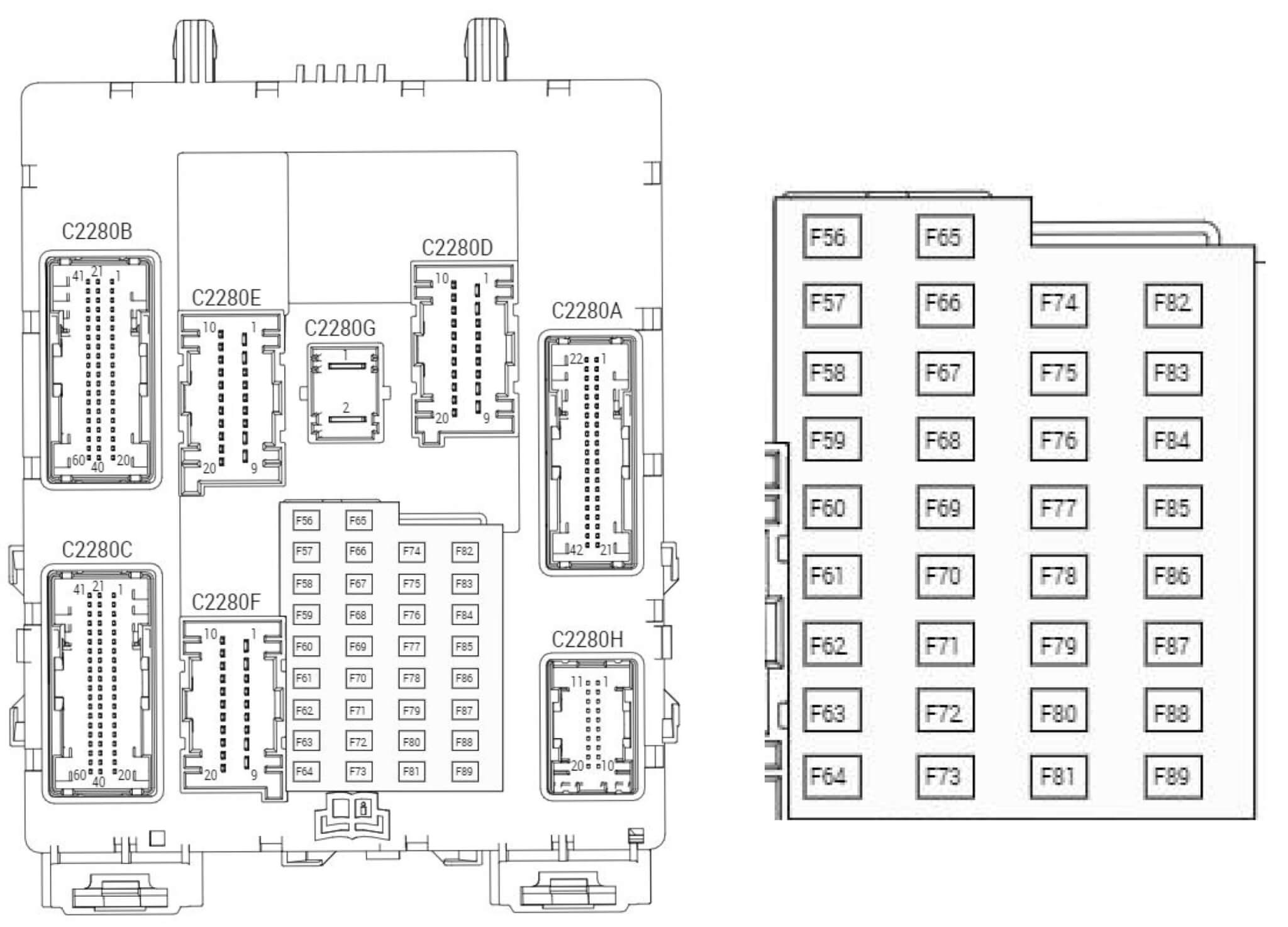
| Fuse Number | Amperage | Circuits Protected |
|---|---|---|
| F56 | 20 | Fuel pump relay, Fuel Pump Control Module (FPCM), Battery Junction Box |
| F57 | — | Not used |
| F58 | 5 | Interior lights relay |
| F59 | 5 | Passive Anti-Theft System (PATS) transceiver |
| F60 | 10 | Luggage compartment lamp, Courtesy lamps, right and left footwells Driver door window control switch Vanity mirror lamp, right and left, Interior/map lamps assemblies Overhead console, Rear interior lamp |
| F61 | 20 | Power point |
| F62 | 5 | Rain sensor module. Light sensor module |
| F63 | 10 | Front sensing module. Forward looking radar |
| F64 | — | Not used |
| F65 | 10 | Liftgate release |
| F66 | 20 | Driver door unlock |
| F67 | 7.5 | SYNC. Multifunction display. Global positioning system module |
| F68 | 15 | Not used (spare) |
| F69 | 5 | Instrument cluster |
| F70 | 20 | Central lock and unlock supply |
| F71 | 7.5 | Heating control head (manual air conditioner). Dual electronic automatic temperature control |
| F72 | 7.5 | Data link connector |
| F73 | 7.5 | Steering wheel module |
| F74 | 15 | Headlamp supply |
| F75 | 15 | Fog lamp |
| F76 | 10 | Reversing lamp |
| F77 | 20 | Washer pump |
| F78 | 5 | Ignition switch. Start button. Keyless vehicle module |
| F79 | 15 | Radio. Electronic finish panel. Hazard light switch. Door lock switch |
| F80 | 20 | Moonroof supply |
| F81 | 5 | Radio frequency receiver supply. Panorama roof power/open |
| F82 | 20 | Washer pump |
| F83 | 20 | Central locking |
| F84 | 20 | Lock/unlock relay Liftgate relay |
| F85 | 7.5 | Electronic 15 feed |
| F86 | 10 | Airbag module. Occupant classification system. Passenger airbag deactivation indicator |
| F87 | 15 | Heated steering wheel |
| F88 | — | Not used |
| F89 | — | Not used |
2019 Escape Fuse Box Diagram for the Luggage Compartment Fuse Box/Rear Junction Box

| Fuse Number | Amperage | Circuits Protected |
|---|---|---|
| F1 | 5 | Hands-free liftgate entry module |
| F2 | 15 | Heated outside mirror (without door control unit). Heated wiper park |
| F3 | 5 | Keyless vehicle door handles |
| F4 | 25 | Door control unit front left |
| F5 | 25 | Door control unit front right |
| F6 | 25 | Door control unit rear left |
| F7 | 25 | Door control unit rear right |
| F8 | 25 | Passenger seat |
| F9 | 25 | Driver seat |
| F10 | 5 | Driver seat memory module logic feed |
| F11 | 5 | Rear ignition coil feed |
| F12 | — | Not used |
| F13 | — | Not used |
| F14 | 25 | High current power windows (front relay) |
| F15 | — | Not used (vehicles with one-touch up power windows) |
| F16 | — | Not used |
| F17 | — | Not used |
| F18 | — | Not used |
| F19 | — | Not used |
| F20 | 5 | Embedded modem |
| F21 | — | Not used |
| F22 | 25 | Heated rear window |
| F23 | 25 | Audio amplifier |
| F24 | 30 | DC/AC power converter |
| F25 | 40 | Trailer tow (vehicles without one-touch up power windows) |
| F26 | 25 | Power liftgate |
| F27 | 20 | Rear power outlet |
| F28 | 20 | Luggage compartment power outlet |
| F29 | 40/30 | Trailer tow (vehicles with one-touch up power windows)/Driver and passenger high current power windows (vehicles without one-touch up power windows). |
| F30 | 5 | Blind spot detection system. Rear view camera with park assist |
| F31 | 5 | Parking aid module |
| F32 | — | Not used |
| F33 | 10 | High current power window switch |
| F34 | — | Not used |
| F35 | — | Not used |
| F36 | — | Not used |
| F37 | — | Not used |
| F38 | — | Not used |
| F39 | — | Not used |
| F40 | — | Not used |
| F41 | — | Not used |
| F42 | — | Not used |
| F43 | — | Not used |
| F44 | — | Not used |
| F45 | — | Not used |
| F46 | 5 | Heated outside mirror relay coil |
| R1 | Relay | Delay accessory relay |
| R2 | Relay | Rear 15 relay |
| R3 | Relay | Heated rear window relay |
| R4 | Relay | Not used |
| R5 | Relay | Not used |
| R6 | Relay | Heated outside mirror relay |
Tips to diagnose electrical issues on your 2006 Explorer
If your power windows don’t work
• In previous model years, Ford used a 30A circuit breaker to provide power to the windows. However, Ford uses different systems in late model vehicles. In some vehicles, each door contains a door module. The window switches are wired to the door module and the module operates the window. This setup is used mainly on vehicles with auto up/down features. In other models, the power windows are operated by the body control module and the motors are fused separately.
If your blower motor doesn’t work
The blower motor gets its power from the blower motor relay power distribution box.
If the circuit you’re working on contains a relay
• A simple way to test a relay is to swap in a similarly shaped relay and see if the component works.
• If that doesn’t work, remove the relay and test for power to the relay control coil and contacts using a multimeter. For more information on relay testing, see this article.
©, 2018 Rick Muscoplat