Fuel gauge not working — how to diagnose and fix
How to diagnose and fix a fuel gauge not working issue
Most common causes of fuel gauge not working
1) Bad connection on top of the fuel tank to the fuel tank sending unit
2) Bent float arm on the fuel sending unit
3) Corrosion on the variable resistor inside the fuel tank
If your fuel gauge used to work and isn’t working now, and you haven’t had any work done on the fuel tank, fuel or fuel pump, chances are high that the electrical connector to the fuel sending unit or the wiring harness to the fuel sending unit is the cause of the problem.
How the fuel sending unit and fuel gauge works
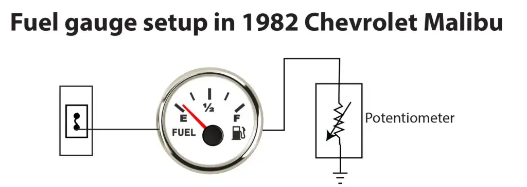
How the fuel gauge works in older vehicles without computers
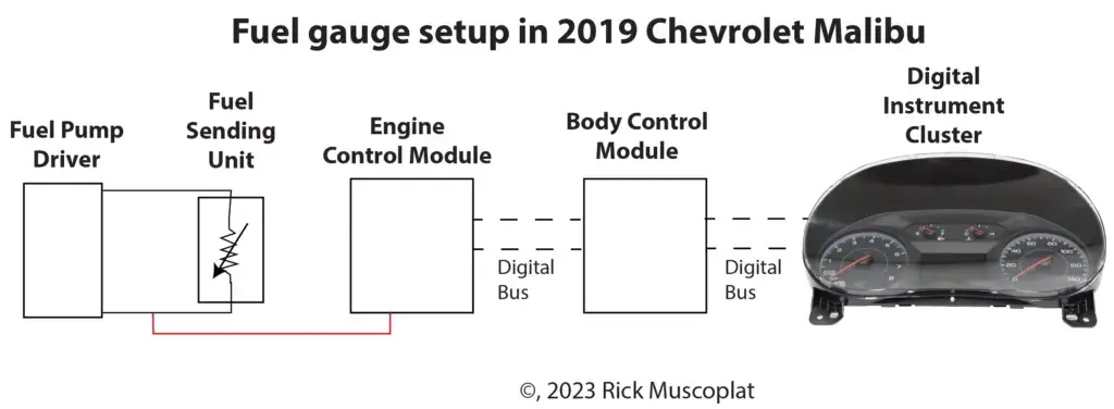
The image below shows how a fuel gauge works in a 1982 and 2019 Chevrolet Malibu. In the 1982 Malibu, the fuel gauge receives power from a fuse. The fuel gauge sends the power to the fuel sending unit potentiometer in the tank. The sending unit potentiometer is connected to a ground point. Based on the resistance provided by the potentiometer, the needle on the fuel gauge moves to the position indicating fuel level.
How the fuel sending unit and fuel gauge work in a 2019 Chevrolet Malibu with computers
The fuel pump driver module provides a reference voltage and ground to the fuel sending unit. The engine control module (ECM) monitors the return voltage from the fuel sending unit. The ECM sends fuel level information on a digital bus to the body control module (BCM). The BCM sends a digital signal to the digital instrument cluster
View live data on your scan tool
Use a scan tool to see what values the BCM is reporting to the instrument cluster (on a late model vehicle). This can save you a lot of time in diagnosing a fuel gauge not working issue. If the BCM is seeing and reporting valid fuel level values, then the problem lies in the data line to the instrument cluster or the stepper motor running the fuel gauge in the instrument cluster.
However, if there’s no fuel level data, then perform the following tests
Start by checking for corrosion in the connector to the fuel level sending unit
The connector is often located on top of the fuel tank or near the top of the fuel tank. Corrosion in the connector can result in erroneous readings. If you find corrosion, use electrical contact cleaner to clean the connector. Dry with compressed air and reconnect. Then check the reading on the instrument cluster.
Check the condition of the fuel sending unit wiring harness
Follow the wiring harness from the tank to the fuel pump driver or ECM to ensure the harness has not been chewed by rodents or abraded. Repair if necessary.
Next, check for power and ground connections for the fuel sending unit, ECM, or BCM
Refer to a shop manual wiring diagram (Alldata or Mitchell) for ground locations
Check the resistance of the fuel level sending unit
Using a multimeter and wiring diagram, check the resistance of the sending unit and compare to known fuel level to determine if the sending unit is reporting accurately.
Refer to a shop manual wiring diagram (Alldata or Mitchell) for expected resistance values.
If the measured values don’t match the expected values, the possibilities are a bent float arm, damaged float or corrosion on the potentiometer. To diagnose further, you will need to remove the sending unit from the tank.
©, 2023 Rick Muscoplat
Posted on by Rick Muscoplat


