GM Charging system problems: Understanding the EPMS system
Learn how to diagnose and fix charging system problems on GM vehicles
The charging systems on late-model GM vehicles are quite different from older stand-alone alternators with internal voltage regulators in prior years. If your GM vehicle has charging system problems, you must first understand how they work before you can diagnose the problem. Plus, you must use a scan tool to determine the root cause. If you don’t, you’ll wind up replacing perfectly good parts. The new GM charging system is called the Electrical Power Management System (EPMS). It’s designed to monitor vehicle voltage and only charge the battery when necessary. GM does this to improve gas mileage and reduce the need to generate power when it’s not needed. The system also monitors the battery to determine its condition and charge it in a way that prolongs its life.
GM’s EOMS maintains electrical system integrity by:
• Monitoring the battery voltage and estimating the battery’s condition.
• Taking corrective actions by boosting idle speed, and adjusting the regulated voltage.
• Notifying the driver of any condition needing attention.
Diagnosing charging system problems on a GM vehicle equipped with the EPMS system
The EPMS system monitors battery usage with the battery current sensor. Based on the data from the current sensor and the charging conditions listed below, the body control module (BCM) determines the best charging routine. Not understanding how the system works can confuse you into thinking the alternator is bad when it’s not even turned on to produce power.
To determine the EPMS charging mode, you’ll need a multimeter and a scan tool with live data. If you skip the scan tool live data review, you’ll set yourself up for failure.
How the EPMS system works to eliminate charging system problems
• The EPMS tests the battery’s condition when the ignition is on and off. When off, the system waits until the vehicle is off for a prolonged period (several hours) before testing for battery condition. Then, it measures open-circuit voltage to determine the battery’s state of charge.
• When the engine is running, the battery rate of discharge is detected by a battery current sensor.
• The current sensor also tests temperature to determine the battery’s state of charge and preferred charging rate.
• The power management system also works with the Body Control Module (BCM) which is connected to the Engine Control Module (ECM) via a data bus.
• The BCM determines the optimal output for the alternator and sends that information to the ECM to control the alternator turn-on signal.
• The BCM then monitors the battery sensor current, the battery positive voltage, and the battery temperature to calculate the battery state of charge. If the charge rate is too low, the BCM performs an idle boost to correct the condition.
How the battery sensor works
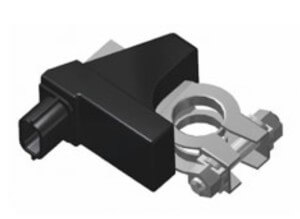
The battery current sensor is connected to the negative battery cable. It has three wires and creates a pulse width modulated(PWM) 5-volt signal with a 0-100% duty cycle. A normal duty cycle is considered to be between 5 and 95%.
When the engine is running, the ECM sends an alternator turn-on signal to the alternator. The alternator’s internal regulator controls the current to the rotor by pulsing the current to obtain the correct output. If the voltage regulator detects a problem, it notifies the ECM by grounding the field current line. The ECM then checks with the BCM to obtain battery temperature and state of charge information.
Suppose the system cannot correct the problem. In that case, it will notify the driver with a charge indicator warning icon and a driver information center message about the SERVICE BATTERY CHARGING SYSTEM (if equipped).
The power management system has six modes of operation
Battery Sulfation Mode– determines the correct charge protocol to correct plate sulfation condition. The BCM enters this mode if the alternator output voltage is less than 13.2 V for 45 minutes. The BCM will enters Charge Mode for 2-3 minutes. The BCM will then determine which mode to enter depending on voltage requirements.
Charge Mode–The BCM will enter Charge Mode when it detects one of the following conditions:
• The wipers are ON for more than 3 seconds.
• The Climate Control Voltage Boost Mode Request) is true, as sensed by the HVAC control head. Ie, you’ve turned on the AC
• The high-speed cooling fan, rear defogger, and HVAC high-speed blower operation are on.
• The battery temperature is less than 0°C (32°F).
• The BCM determines that the battery state of charge is less than 80 percent.
• The vehicle speed is greater than 90 mph. (No need to save gas at that point)
• The battery current sensor is showing a fault
• The system voltage is below 12.56 V
When any one of these conditions is met, the system will set the targeted alternator output voltage to 13.9-15.5 V, depending on the battery state of charge and estimated battery temperature.
Fuel Economy Mode–The BCM will enter Fuel Economy Mode when the battery temperature is at least 32°F but less than or equal to 176°F, the calculated battery current is less than 15 amps but greater than -8 amps, and the battery state-of-charge is greater than or equal to 80 percent. At that point, the BCM targets alternator output at 12.5-13.1 V. to save gas.
Headlamp Mode–The BCM boosts alternator output to 13.9-14.5 V whenever the headlights are turned on.
Start-Up Mode–The BCM commands a voltage of 14.5 volts for 30 secs after startup.
Voltage Reduction Mode–The BCM enters the Voltage Reduction Mode when the ambient air temperature is above 32°F, the battery current is less than 1 amp and greater than -7 amps, and the generator field duty cycle is less than 99 percent. The BCM targets output to 12.9 V. The BCM exits this mode once the criteria for Charge Mode are met.
©, 2014 Rick Muscoplat
Posted on by Rick Muscoplat
