
Throttle position sensor TPS
Diagnose and replace throttle position sensor TPS
What does a throttle position sensor do?
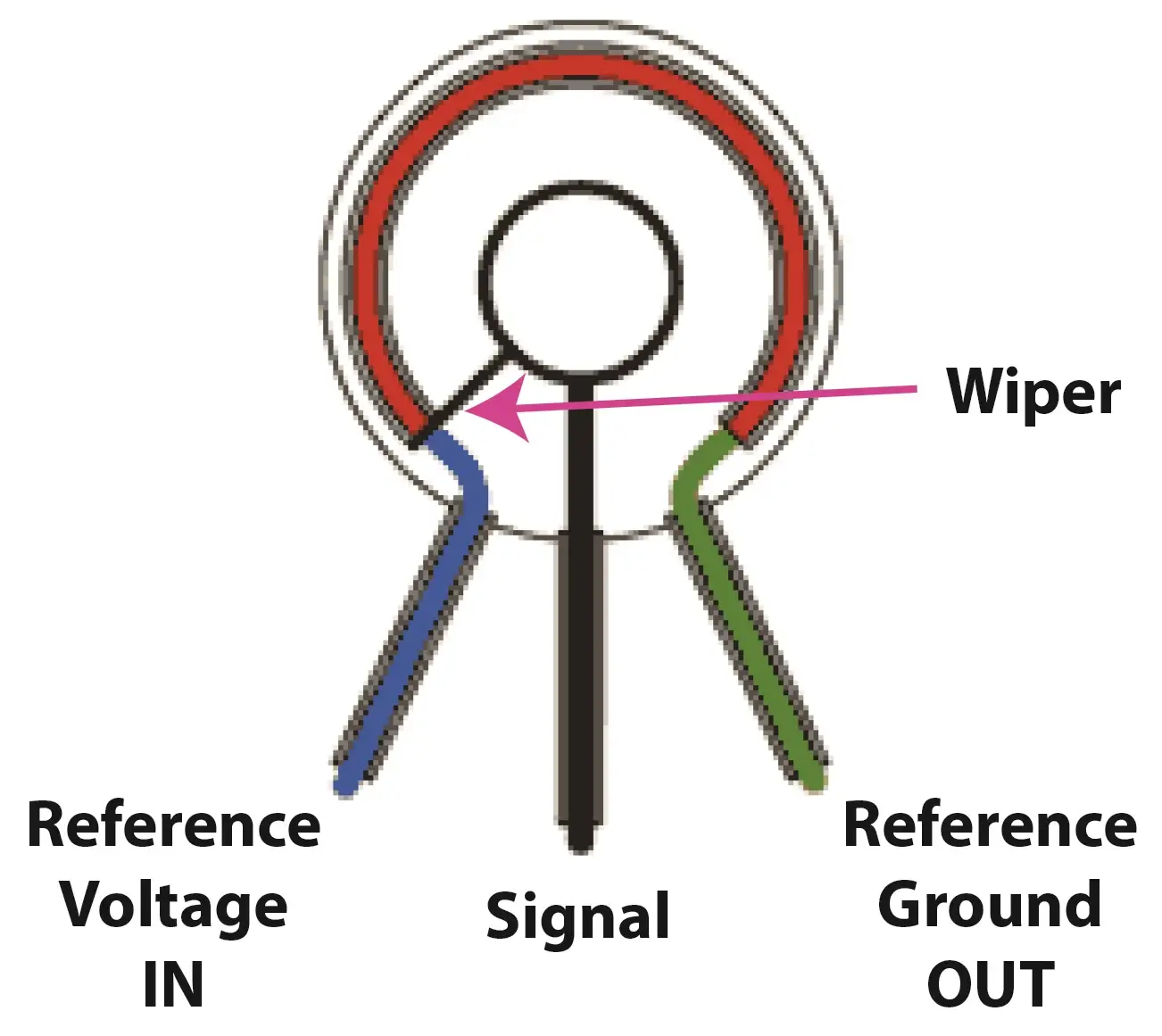
A throttle position sensor is a potentiometer that changes voltage as it moves. It’s tells the ECM how far the driver is opening the throttle. In older vehicles it’s mounted right on the throttle body. However, in newer cars, the TPS is located right on the gas pedal inside the cabin. The manufacturers eliminated the cable to the throttle body and rely instead on stepper motors to open and close the throttle plate.

What goes wrong with a throttle position sensor
Since the TPS is a rotating potentiometer, it can wear out portions of the sensor, especially sections that are used most often. When that happens, the ECM sees a clean change in voltage and then a dropout of signal, resulting in a stumble or hesitation.
If the dropout is too great, or the signal isn’t clean, the ECM will set a trouble code.
How to diagnose a throttle position sensor TPS
 The ECM sends a constant 5 volt reference signal to the variable resistor (potentiometer) inside the TPS case.
To detect whether the reference signal arrived safely, it also monitors the return ground back at the computer.
So all the tests you perform must be done with the connector still connected to the TPS and the key turned to the RUN position. So you will have to backprobe the connector to monitor voltage readings.
Check for reference voltage to the throttle position sensor
Using a multimeter, connect one lead of your digital voltmeter to the 5V reference in wire and the other to a good ground. The reading must be 5 volts. If it isn’t, you’ve either got a break in the wire between the ECM and the TPS, or you have a bad ECM. Find the 5v reference wire in the ECM connector and check for it there. If you get 5 volts there, that confirms a broken wire.
Check for ground
Next, check for reference return ground. Disconnect the TPS connector and place one lead of your meter on the 5 volt reference signal IN pin and the other on the reference ground. It must read 5 volts. If it doesn’t, follow the same procedure at the ECM that you used to check for reference voltage.
Check TPS signal
Reconnect the connector to the TPS and then test the TPS signal. This one can be a bit tricky. Most pros use a lab scope for this check because it will show a gradual sweeping curve as you open the throttle. If there are any dead spots (or static) in the TPS signal, it shows up dramatically on the scope. A digital voltmeter, on the other hand, averages the voltage readings as you open the throttle. So a quick dropout it harder to detect. That’s why it’s important to perform the TPS voltage test slowly if you’re using a digital meter.
Some TPS sensors have a 4th wire. Manufacturers use the 4th wire to tell the computer when the TPS is at “0.” When the wiper returns to the “off” stop, it opens a switch, cutting off TPS voltage. If your TPS only has 3 wires and it tests as bad, you may have to follow a special alignment procedure when installing the new sensor. The alignment/adjustment procedure is designed to make sure the “off” voltage falls within a certain acceptable range for the PCM. If you don’t adjust it properly, the PCM may think that the throttle is partially open, when it is really closed.
How to replace a throttle position sensor
If the TPS is mounted on the throttle body, remove the screws  holding it in place. Sometimes, the screws are security torx screws, so you’ll need security torx bits. When installing the new TPS, you may need an alignment tool (sometimes comes with the new sensor), or you’ll have to adjust the sensor to a specific resistance value shown in the shop manual.
© 2012 Rick Muscoplat
Posted on by Rick Muscoplat