
2009 Ranger Fuse Diagram
2009 Ranger Fuse Diagram
This 2009 Ranger Fuse Diagram post shows two fuse boxes; the Battery Junction Box/Power Distribution Box located under the hood and the Smart Junction Box/Passenger Compartment Fuse Panel
There’s lots more information on this site for your vehicle.
To find fuse diagrams, click here
To find Relay locations, click here
To find Sensor Locations, click here
To find Module Locations, click here
To find Switch Locations, click here
To find Firing Order, click here
To find the most common trouble codes and fixes for your vehicle, click here
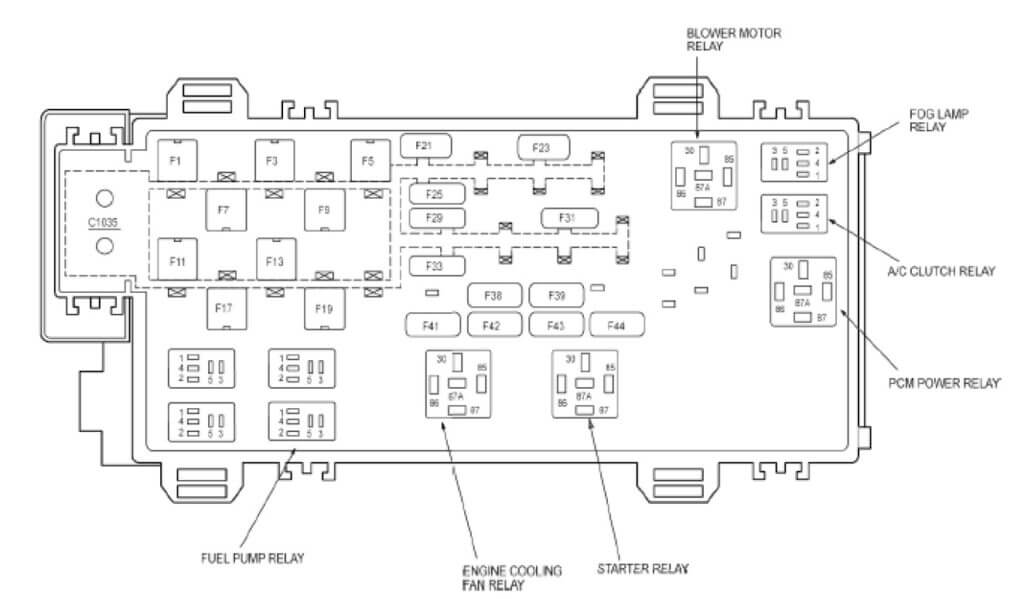
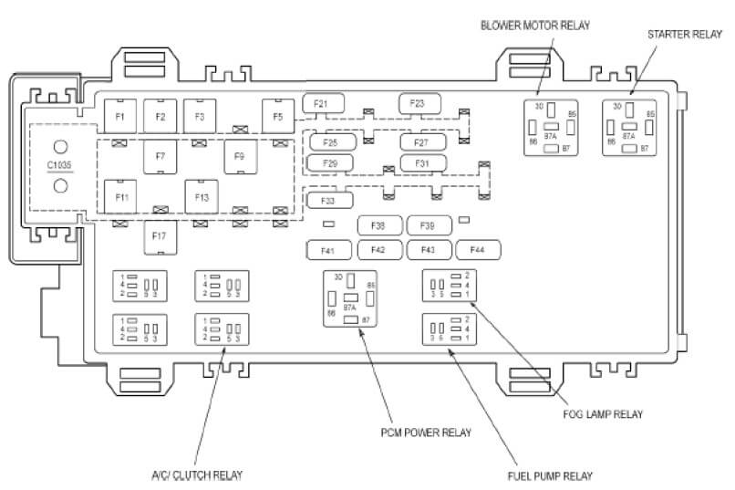
2009 Ranger Fuse Diagram for Battery Junction Box 2.3L engine
1 40A Smart Junction Box (SJB)
2 – Not Used
3 40A Smart Junction Box (SJB)
4 – Not Used
5 50A Smart Junction Box (SJB)
6 – Not Used
7 40A Starter Relay
8 – Not Used
9 40A Ignition Switch
10 – Not Used
11 30A PCM power relay
12 – Not Used
13 30A Blower motor relay
14 – Not Used
15 – Not Used
16 – Not Used
17 40A Anti-lock Brake System (ABS) module
18 – Not Used
19 20A Engine cooling fan relay
20 – Not Used
21 10A Powertrain Control Module (PCM), Evaporative emission (EVAP) canister vent valve
22 – Not Used
23 30A Fuel Pump Relay, Fuel injectors
24 – Not Used
25 10A A/C clutch relay
26 – Not Used
27 – Not Used
28 – Not Used
29 30A Windshield wipers/washer
30 – Not Used
31 15A Fog lamp relay
32 – Not Used
33 30A Anti-lock Brake System (ABS) module
34 – Not Used
35 – Not Used
36 -Not Used
37 – Not Used
38 7.5A Trailer tow connector – Right turn
39 15A Powertrain Control Module (PCM)
40 – Not Used
41 10A 5R44E Transmission
42 7.5A Trailer tow connector – Left turn
43 20A EVAP canister purge valve, Engine cooling fan relay, Idle Air Control (IAC) valve, Heated Oxygen Sensor (HO2S) #11, Heated Oxygen Sensor (HO2S) #12, Mass Air Flow/Intake Air Temperature (MAF/IAT) sensor, EGR stepper motor, A/C relay coil
44 15A Ignition coil, Ignition transformer capacitor 1
1 40A Smart Junction Box (SJB)
2 – Not Used
3 40A Smart Junction Box (SJB)
4 – Not Used
5 50A Smart Junction Box (SJB)
6 – Not Used
7 30A Starter Relay
8 – Not Used
9 40A Ignition Switch
10 – Not Used
11 30A PCM power relay
12 – Not Used
13 30A Blower motor relay
14 – Not Used
15 – Not Used
16 – Not Used
17 40A Anti-lock Brake System (ABS) module
18 – Not Used
19 – Not Used
20 – Not Used
21 10A Powertrain Control Module (PCM), Evaporative emission (EVAP) canister vent valve
22 – Not Used
23 30A Fuel Pump Relay, Fuel injectors
24 – Not Used
25 10A A/C clutch relay
26 – Not Used
27 20A 4X4 control module
28 – Not Used
29 30A Windshield wipers/washer
30 – Not Used
31 15A Fog lamp relay
32 – Not Used
33 30A Anti-lock Brake System (ABS) module
34 – Not Used
35 – Not Used
36 – Not Used
37 – Not Used
38 7.5A Trailer tow connector – Right turn
39 15A Powertrain Control Module (PCM)
40 – Not Used
41 10A *5R44E Transmission
42 7.5A Trailer tow connector – Left turn
43 20A EVAP canister purge valve, Heated Positive Crankcase Ventilation (PCV) valve, Idle Air Control (IAC) valve, Mass Air Flow/Intake Air Temperature (MAF/IAT) sensor, Heated Oxygen Sensor (HO2S) #11, Heated Oxygen Sensor (HO2S) #12, Heated Oxygen Sensor (HO2S) #21, Heated Oxygen Sensor (HO2S) #22, EGR vacuum regulator solenoid valve, A/C relay coil
44 15A Ignition coil, *Ignition transformer capacitor 1
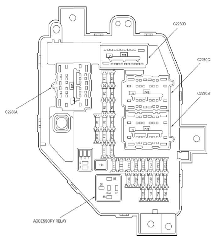
2009 Ranger Fuse Diagram for Smart Junction Box
1 5A Illumination dimmer
2 10A Trailer tow connector – Park
3 10A Headlamp, right (Low beam lamp feed)
4 10A Headlamp, left (Low beam lamp feed)
5 5A Windshield wiper module
6 10A Audio unit, Door lock switch illumination
7 5A Not Used
8 10A Restraints Control Module (RCM), Occupant Classification System Module (OCSM),
passenger Air bag Deactivation (PAD) Indicator
9 5A Instrument Cluster (IC), Air bag indicator
10 10A 4X4 control module, Instrument Cluster (IC)
11 10A Smart Junction Box (SJB), logic power
12 15A Subwoofer amplifier with audiophile, Satellite radio receiver
13 15A Interior lamp relay, Horn relay
14 15A High beam lamp feed to High beam indicator, Headlamp, right, Headlamp, left
16 30A Accessory relay (Power windows)
17 15A Indicator flasher relay
18 – Not Used
19 20A Brake pedal position switch (Stoplamps)
20 10A Transmission control switch, Digital Transmission Range (TR) sensor, Speed control
servo, Anti-lock Brake System (ABS) module, Indicator flasher relay, Reversing lamps
switch, Speed control On/Off switch, Speed control Set/Resume switch
21 5A Digital Transmission Range (TR) sensor, Starter relay, Powertrain Control Module (PCM)
22 5A Audio unit
23 30A Main light switch, Multifunction switch
24 20A Audio unit
26 2A Deactivator switch
27 10A Blend door actuator, Climate control assembly
28 15A 4X4 control module
29 20A Cigar lighter, front, Data Link Connector (DLC)
30 5A Exterior rear view mirror switch
31 20A Park lamp relay
32 5A Brake pedal position switch (logic power), Brake shift interlock
33 5A Instrument Cluster (IC), Neutral tow indicator
34 20A Power point
35 15A Door lock/unlock relay, Driver door unlock relay