
Troubleshoot Your Car’s AC System: DIY Diagnostic Tests
A Step-by-Step Guide to Troubleshoot Your Car’s AC
I’ll assume you’ve already added refrigerant to your car’s AC system, but it still isn’t putting out cold air. So what’s next? Are you going to replace the compressor, expansion valve, or evaporator temp sensor? Stop! Don’t replace anything until you troubleshoot your car’s AC system.
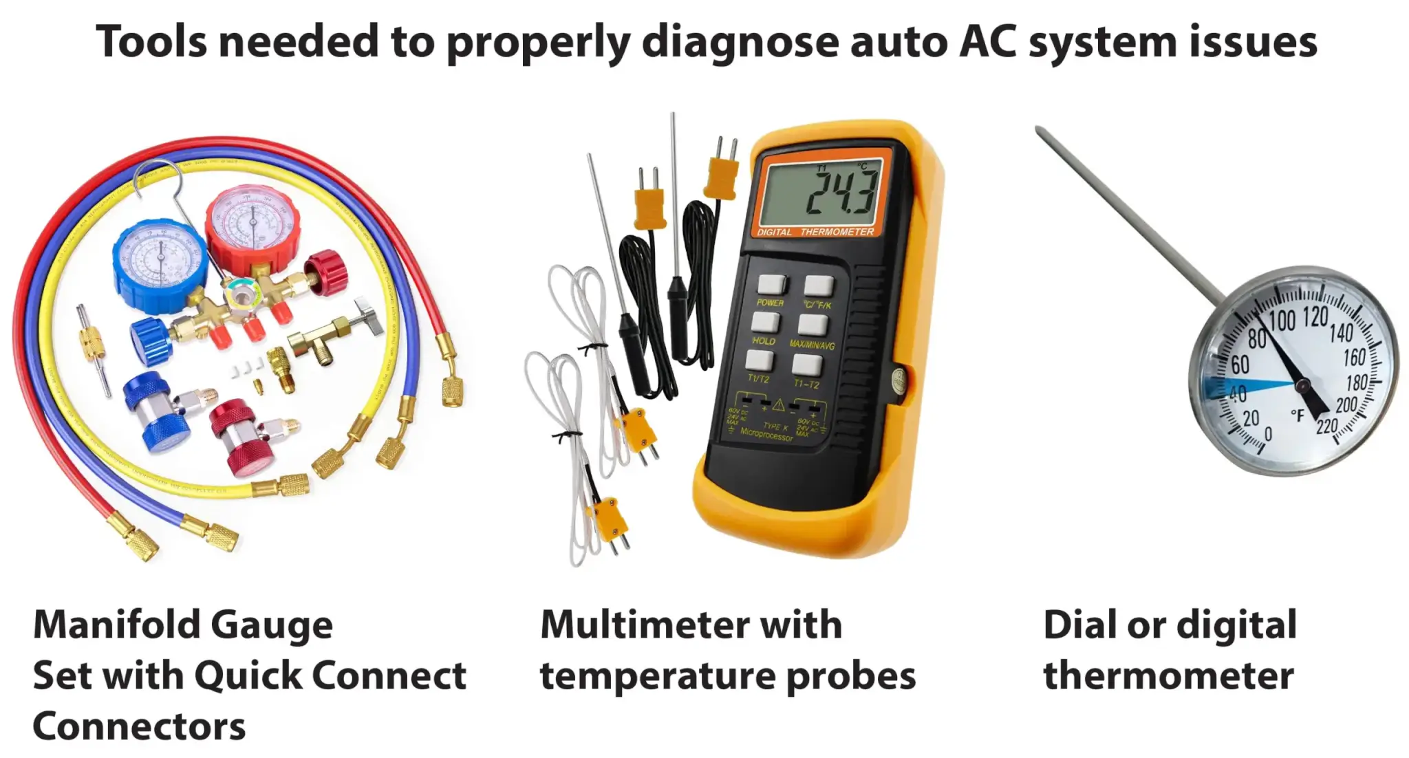
Here are the tools you’ll need to troubleshoot your car’s AC problems professionally
You’re kidding yourself if you think you can diagnose car AC problems with just the gauge on a DIY recharging kit. At the very least, you need to see the high and low side pressures and compare the readings to the outside and center duct temperatures. Even then, you still might not have the complete picture of your AC system’s condition.
If you invest around $100 in tools, you can perform the same diagnostic tests the pros use. Here’s what you’ll need. If you own and can borrow a scan tool with live data, you can check the sensor readings on the screen instead of connecting your meter to the sensors.
• A manifold gauge set. You can buy one for as little as $40
• A multimeter with temperature probes
• A probe thermometer
Start by checking your AC system’s static pressure
Static pressure is the refrigerant pressure with the engine and compressor off and the AC not running for at least 1 hour, so the high and low sides are equalized. The pressure/temperature chart shown below can give you a rough idea of system pressure at rest.
• Attach the high and low side connectors to the high and low ports and note the pressures on both gauges.
• The pressures should be the same on both gauges. If they’re different, there’s a problem.
• Measure the temperature in the engine compartment
• Using the pressure on your gauges and the ambient temperature reading you got from under the hood, find the expected pressure reading in the chart below.
• The static pressure must be above 40 psi. for the compressor to operate
NOTE: The static pressure reading doesn’t tell whether the system is fully charged. It only tells you if the pressure is high enough to allow the compressor clutch to operate or if the system is mostly or discharged.
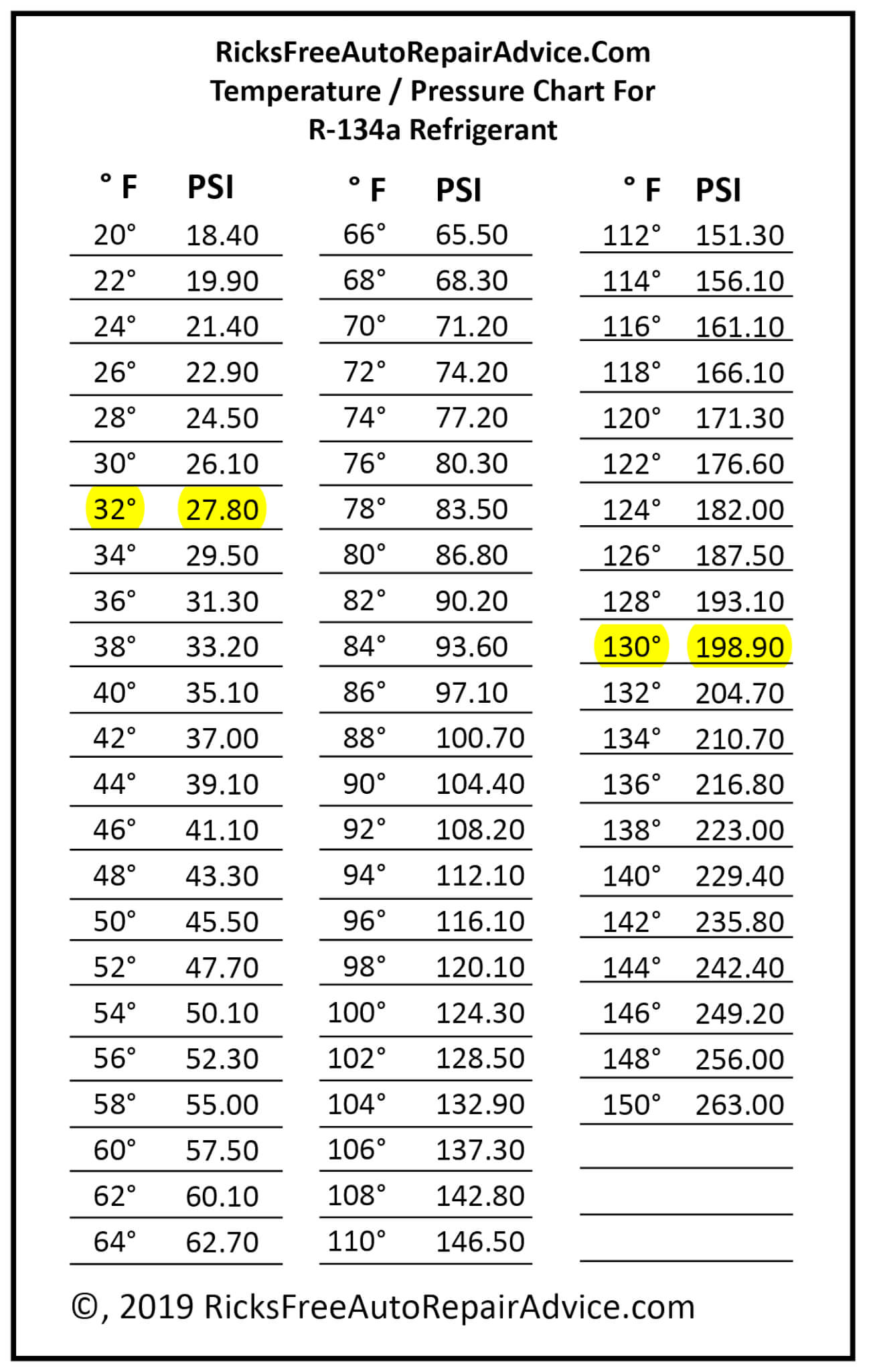
The static pressure chart shows what refrigerant pressure should be compared to ambient temperature.
NOTE: If the ambient temperature is above 60°F and the static pressure reading is below 30 psi, your AC system has a serious leak. That leak must be fixed before you can proceed. Here’s why. When you have a leak this large, you have lost some oil and most likely have air in the system. Adding refrigerant without finding and fixing the leak will get you colder air temporarily, but that refrigerant will leak out, and running the system with low oil and air will cause significant and very expensive problems later.
Next, check the radiator fan operation, condenser fins for debris or damage, and the operation of the ambient temperature sensor (if equipped)
Most DIYers skip these tests. That’s huge mistake. If the radiator fans aren’t working properly, the condenser fins are clogged, or the ambient temperature sensor is off or not working, all the rest of the tests can lead you to a false conclusion!
Check the radiator fans
If you have two radiator fans, they should both be running when you turn on the AC. If not, fix the fan problem first using the shop manual’s diagnostic procedure. If you just have a single fan, it’s mostly likely a multi-speed fan. If should be running at maximum speed when the AC is on. If not, troubleshoot the problem.
Check the condenser fins
The condenser is located in front of the radiator, directly behind the grille. The condenser’s job is to remove heat from the refrigerant vapor, allowing the refrigerant vapor to condense back into a liquid.
To properly condense the hot refrigerant, it needs the proper airflow across the condenser fins. If the fins are bent or filled with bug debris, mud, or sand, the condenser can’t do its job, and that reduces overall cooling.
Check for good airflow across the Evaporator
The evaporator coil is located behind the dash, inside the heater box. Its job is to remove heat and moisture from the cabin air. To do that, it needs good airflow. Turn the blower speed to high and the mode to dash vents and MAX AC. You should feel strong airflow through the dash vents.
If you don’t get maximum airflow, check the condition of the cabin air filter (if equipped). Also, check for a clogged evaporator coil. (Remove the blower motor resistor from the lower duct and use a flashlight to view the evaporator. Or, use an inexpensive borescope with your cell phone).
Check the ambient temperature sensor
Vehicles equipped with auto climate control have an ambient temperature sensor. If the ambient temperature sensor isn’t working, it will prevent the AC compressor clutch from engaging.
Use a scan tool with live data to read the ambient temperature sensor readings and compare them to the actual ambient temperature. If the readings are way off, fix the sensor before proceeding.
All the above checks are good: Time to test running pressures
Check the High and low side pressure readings
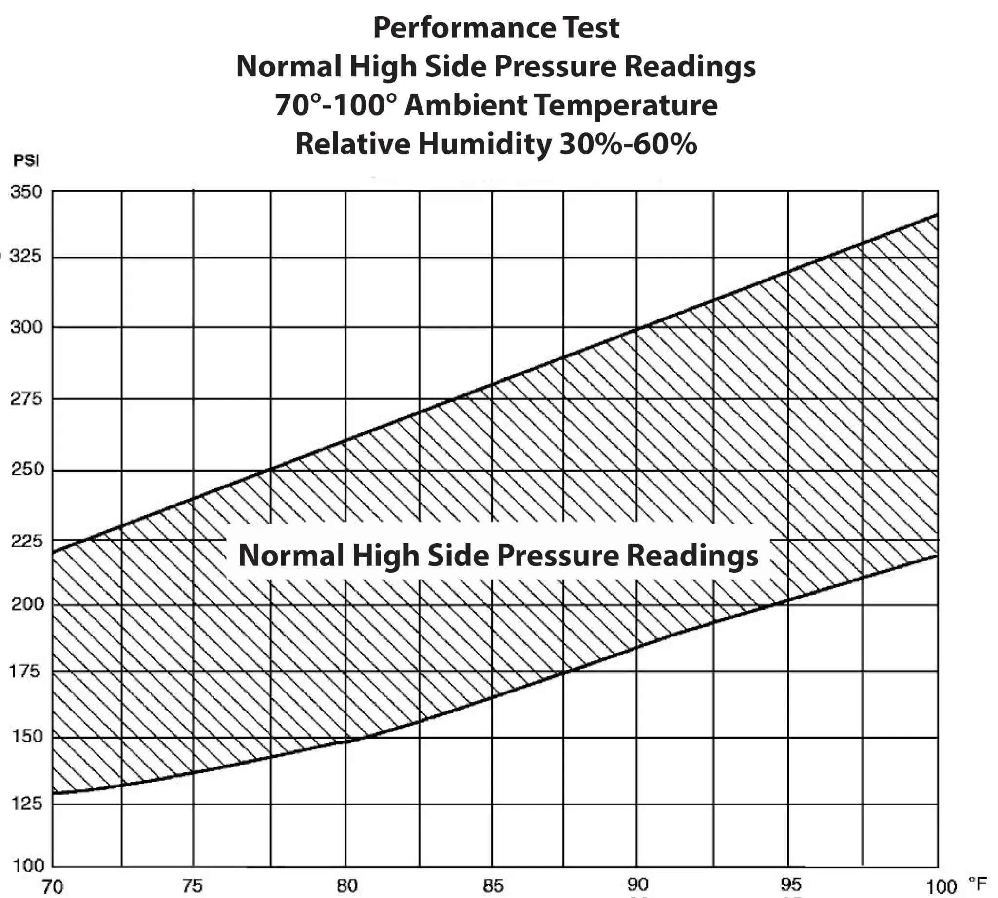
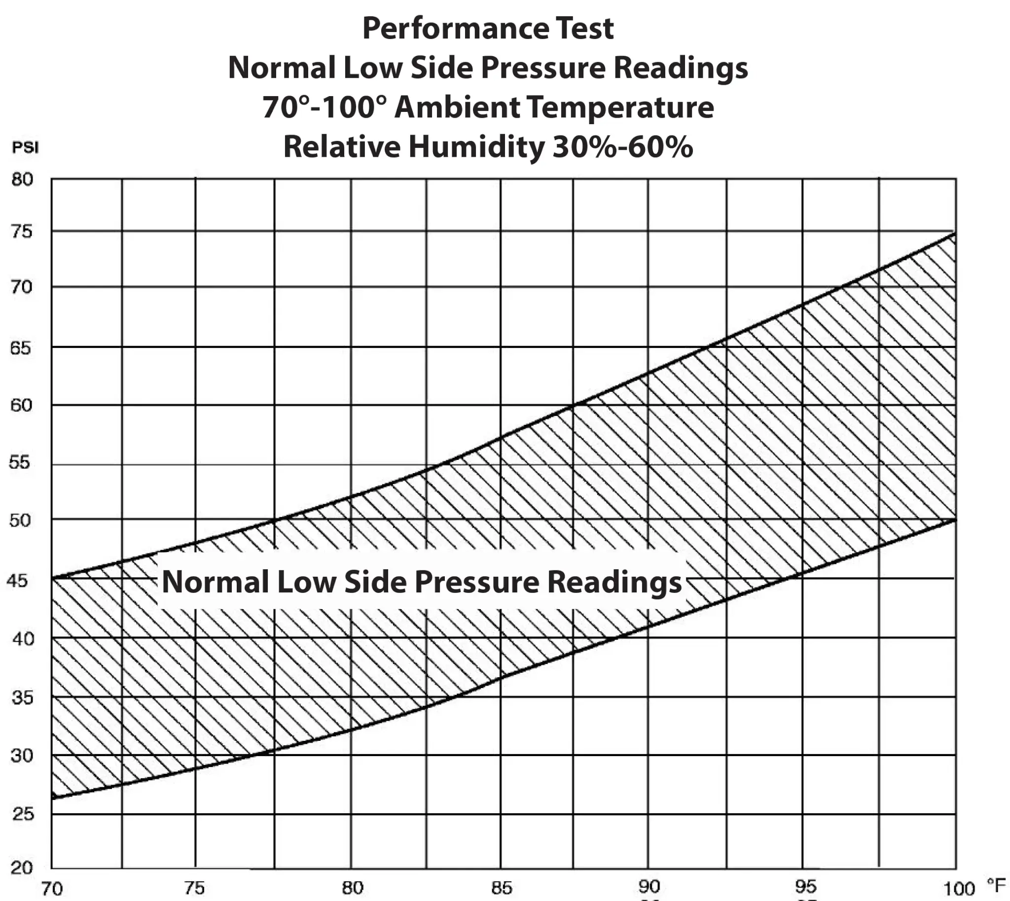
Connect your manifold gauge set to the high and low side ports. Run the system on MAX AC for at least five minutes. Then, use the pressure charts below to determine if your system pressures are normal.
If the pressures are normal, but you’re still not getting cold air, you’ll have to conduct a performance test, like the one shown below.
Conduct a performance test
A performance test uses pressure readings, ambient temperature and humidity readings, and center duct temperature to give you a rough idea of the system’s performance. The exact set-up procedure differs by vehicle make, model, and year, so you must consult your vehicle’s shop manual.
Some carmakers want this test done with the doors and windows, while others want the doors and windows closed. The same applies to engine RPM and blower motor speed during the test. There is no one-size-fits-all when it comes to performance testing.
Here is an example of the testing specs for a 2005 Ford Explorer
• Drive the vehicle or run the engine until it reaches normal operating temperature.
• Open all vehicle windows and leave the hood open for the test. Open the rear hatch and/or rear doors (if equipped).
• If the vehicle is equipped with auxiliary climate control, set the auxiliary controls to full COOL in the PANEL mode at HI blower speed.
• Set the climate controls.
For a manual system, set the AC controls to ON, the mode to DASH VENTS, the dash temp controls to FULL COLD, the recirculation to FRESH AIR, and the blower to HIGH speed.
For Automatic Temperature Systems, set the AC to ON. If the vehicle has an A/C switch or compressor on the switch, set it to A/C ON. Set the temperature to 60°F. If the vehicle has dual-function temp controls, disable the dual function. Set the blower to HIGH speed. Set the recirculation to FRESH AIR.
• Start the engine. Ensure the compressor is running. Allow the vehicle to run at idle speed until the suction (low-side) and discharge (high-side) pressures are stable or fluctuate in a repeating range.
• Record the ambient (shop) temperature.
• Record the discharge pressure. If the pressure is fluctuating, record the average value.
What did the performance test tell you?
It tells you whether system pressures are within normal limits. If the pressures are outside normal limits, consult the symptom charts in the shop manual.
Here are some examples of what you’ll find in the symptom charts
• If high and low side pressures are too high, you may have inadequate airflow across the condenser
• If the high side is too high but the low side is normal, you may have a refrigerant overcharged or air in the system
• High side pressure is low, and the low side is low, or the compressor is cycling, you may have a low refrigerant charge, the AC suction line partially restricted or plugged, the AC cycling switch is sticking
Now the gold standard: Troubleshoot your car’s AC by performing a heat load test
The procedures for conducting heat load testing vary based on the type of expansion device your system uses.
All AC systems work by metering high-pressure liquid refrigerant into the evaporator coil. However, the type of metering device varies by car maker and model year. Testing is based on the type of expansion valve.
If you know which types your vehicle uses, skip down to the testing procedure for your expansion device. Otherwise, read the descriptions, view the images, and determine the type of vehicle you are using.
Here are the types:
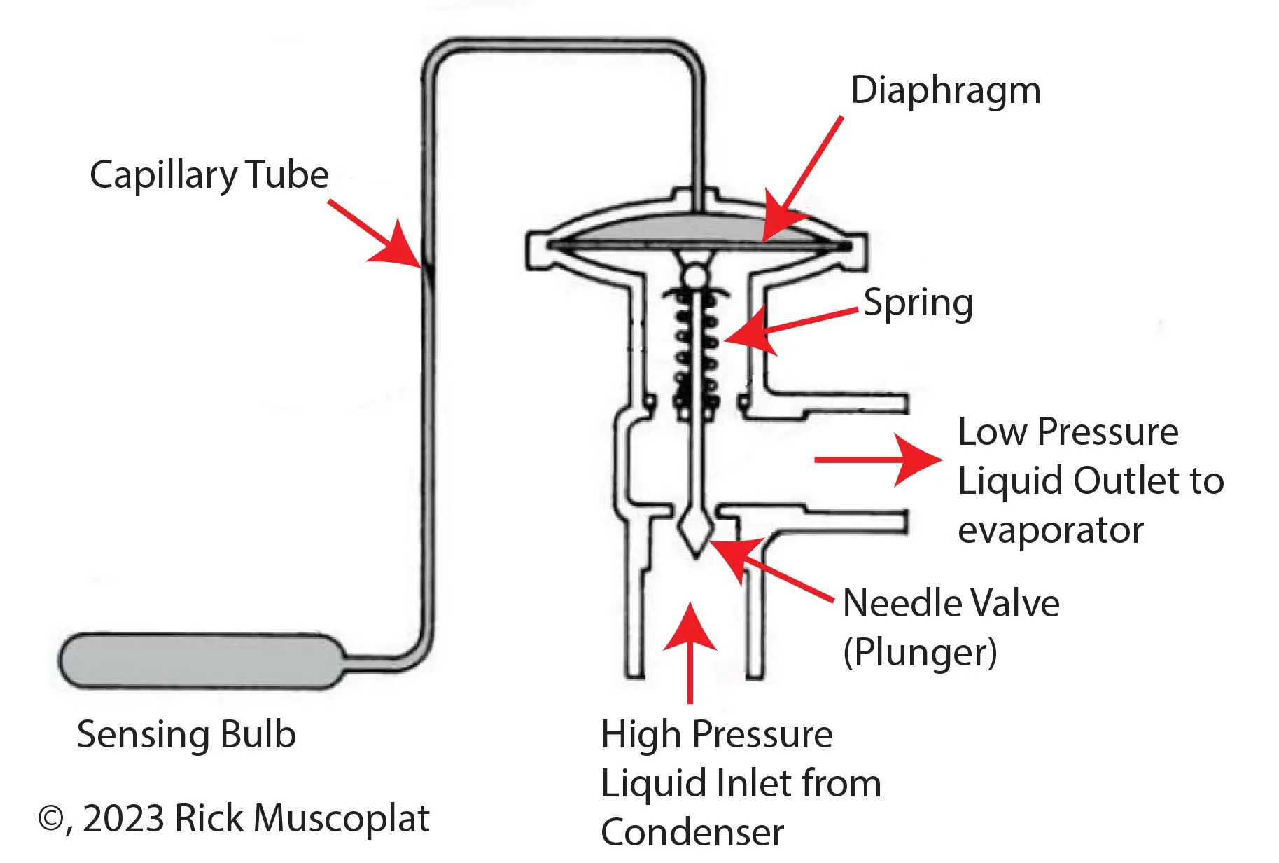
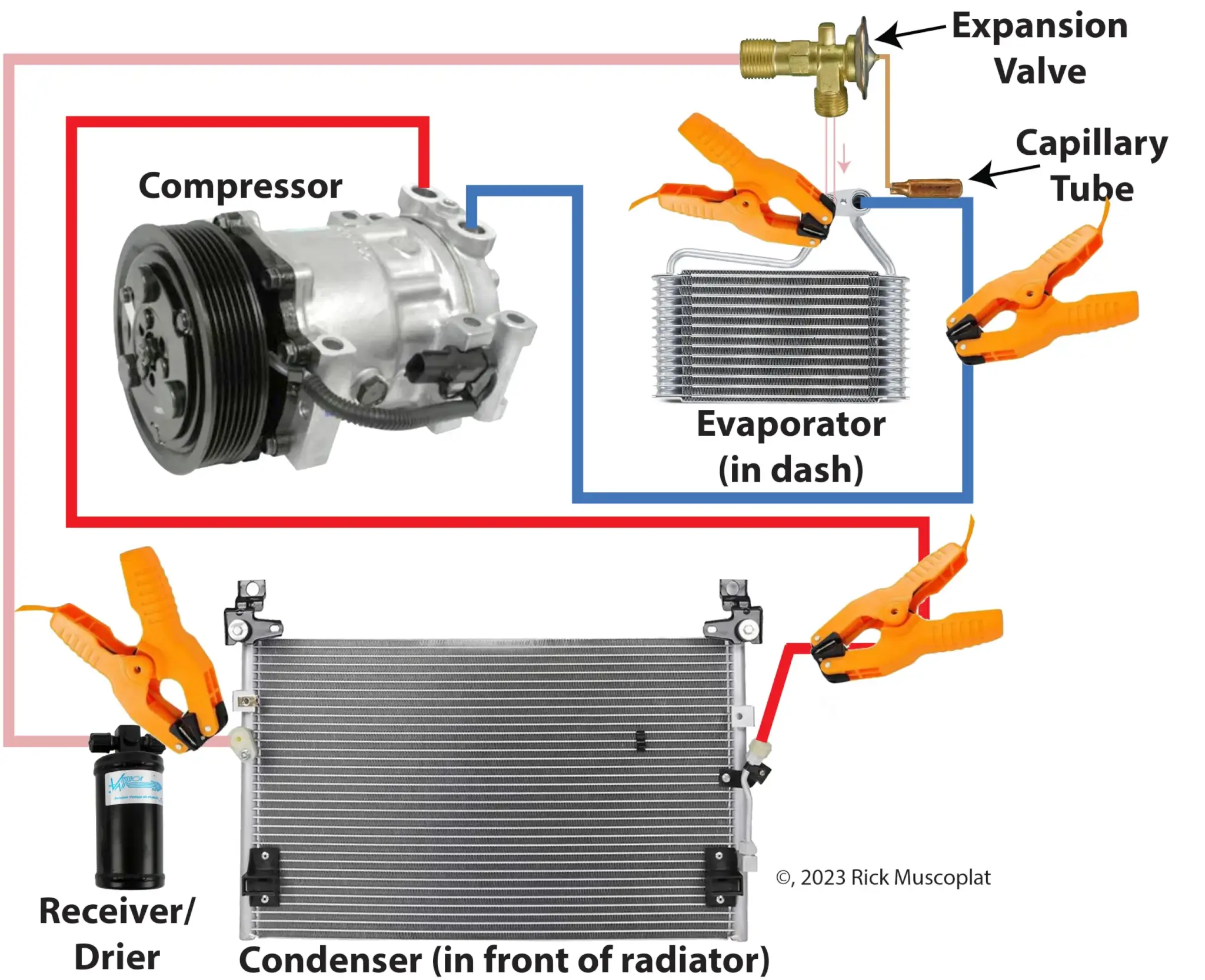
Capillary tube expansion valve
This expansion valve incorporates a metering 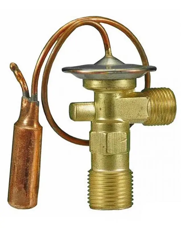 plunger connected to a diaphragm encased in a sealed chamber with refrigerant gas on one side of the diaphragm. A tube filled with the same refrigerant leads from the top of the chamber to a sensing bulb attached to the outlet of the evaporator. As the warm refrigerant leaves the evaporator coil, the heated outlet tubing warms the sensing bulb. The refrigerant in the bulb boils, increasing pressure at the top of the sealed chamber, causing the plunger to allow more liquid refrigerant into the evaporator. The additional refrigerant causes the evaporator outlet temperature to drop, which reduces boiling and pressure in the sensing bulb. The reduced pressure causes the diaphragm to relax and shut off refrigerant flow to the evaporator coil.
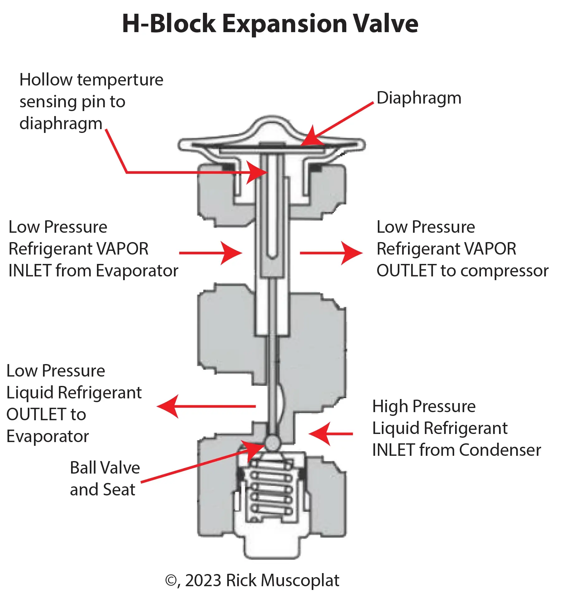
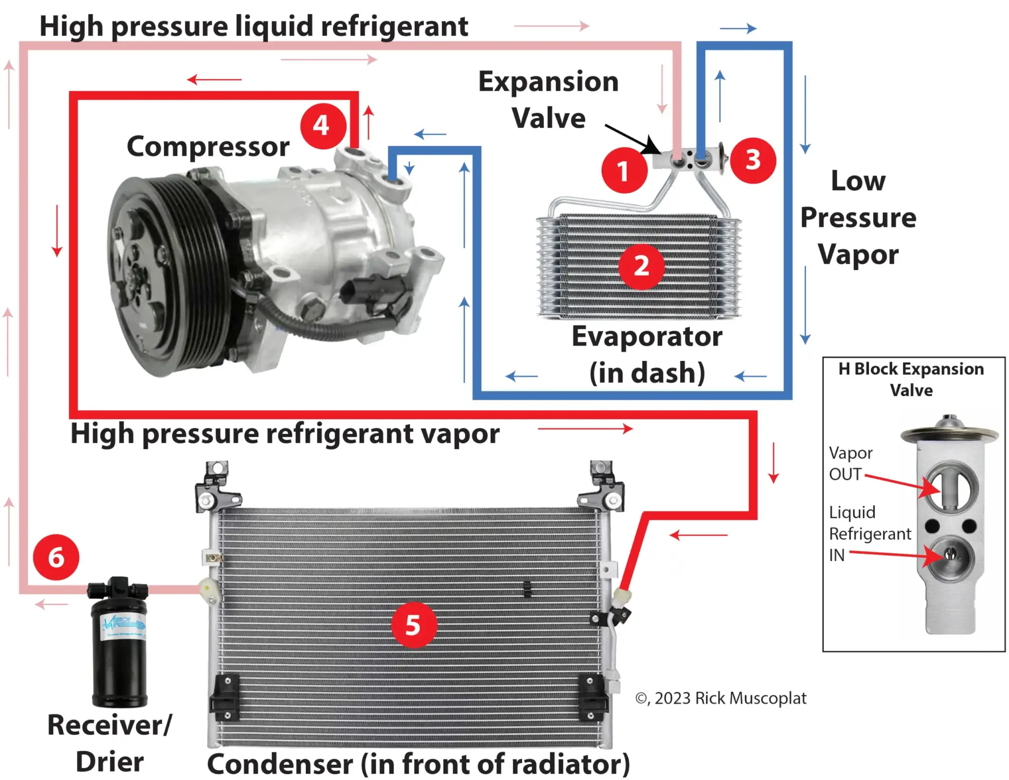
H-block Expansion Valve
The H-block expansion valve works much like
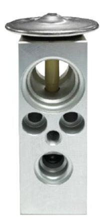
H-block style expansion valve
the capillary tube valve, except that it doesn’t use a remote-sensing bulb. It’s mounted on the outlet of the evaporator and directly senses the temperature of the refrigerant leaving the evaporator. A hollow rod runs through the center of the vapor port and transfers that exiting vapor temperature up to the diaphragm. As the temperature changes, the diaphragm moves up and down and moves the ball valve off its seat, metering liquid refrigerant into the evaporator.
Fixed Orifice tube and Variable Orifice tube expansion devices
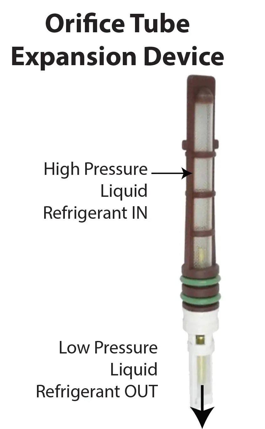
As the name implies, a fixed orifice tube is a liquid metering device with a fixed tube diameter. A variable orifice tube contains a temperature-sensitive spring and needle valve that varies the amount of liquid refrigerant that flows through the tube.
The orifice tube can be located in the inlet to the evaporator or in the high pressure liquid line. High pressure liquid refrigerant enters orifice tube through the screen filter and exits the tube as low pressure liquid. Orifice tubes are color coded according to the tube diameter which can vary from .067″ – .047″.
How each expansion device system works
How a capillary tube expansion valve car AC system works
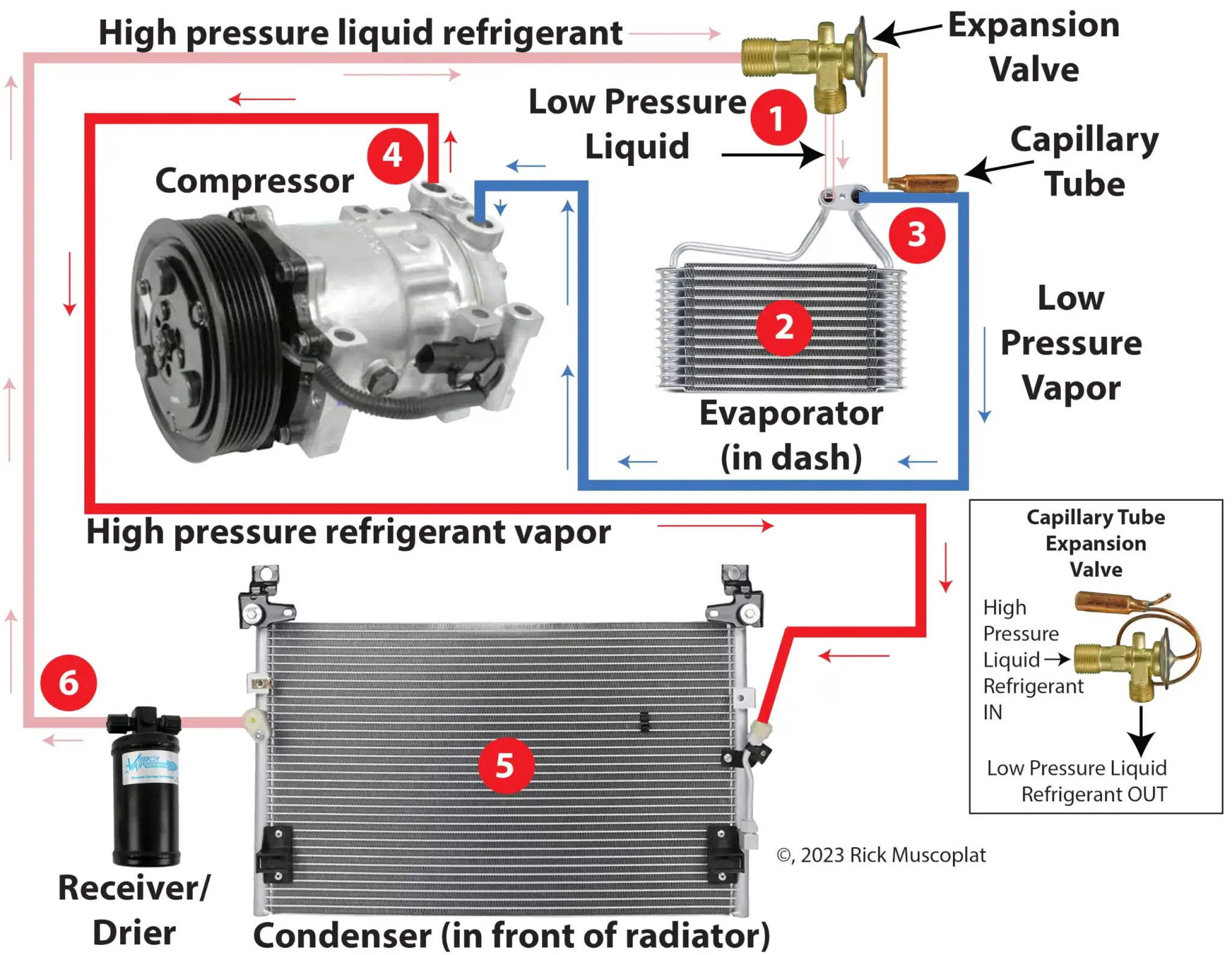
1) High-pressure liquid refrigerant enters the capillary tube expansion valve. Based on the temperature at the sensing bulb attached to the evaporator outlet, the expansion valve meters the correct amount of liquid refrigerant into the evaporator. The refrigerant leaves the expansion valve as a low-pressure liquid.
2) The liquid refrigerant fills the evaporator and absorbs the heat from the cabin air as the air flows across the evaporator fins. The absorbed heat causes the refrigerant to change from a liquid to a vapor (gas).
3) The refrigerant vapor leaves the evaporator and is sucked into the compressor.
4) The compressor converts the low-pressure vapor into a high-pressure vapor, causing it to heat up.
5) The heated high-pressure vapor enters the condenser and is cooled by airflow across the condenser fins. Heat is removed from the vapor, and it condenses into a high-pressure liquid.6) The high-pressure liquid refrigerant flows into the receiver/drier, where a desiccant bag removes moisture from the liquid.
How an H-Block Expansion valve car AC system works
How an Orifice Tube Expansion device car AC system works
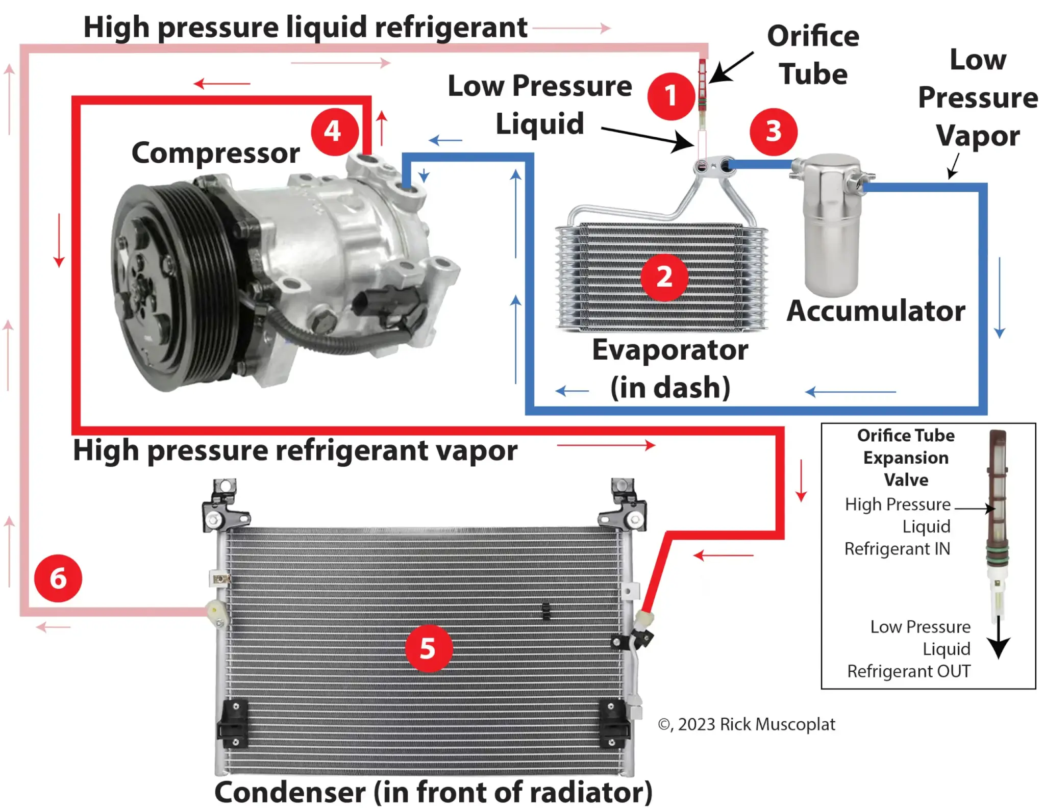
1) High-pressure liquid refrigerant enters the orifice tube through the screen mesh. The liquid refrigerant flows through the open orifice tube and into the evaporator, changing from a high-pressure liquid to a low-pressure liquid as it leaves the orifice tube.
2) The liquid refrigerant fills the evaporator and absorbs the heat from the cabin air as the air flows across the evaporator fins. The absorbed heat causes the refrigerant to change from a liquid to a vapor (gas).
3) The refrigerant vapor leaves the evaporator and enters the accumulator.
4) The compressor can only compress gas. If any liquid refrigerant enters the compressor, it can destroy it. So, the accumulator collects any liquid that may have left the evaporator and allows it to evaporate into a vapor before entering the compressor. The accumulator contains a desiccant to remove any moisture in the refrigerant.
4) The compressor converts the low-pressure vapor into a high-pressure vapor, causing it to heat up.
5) The heated high-pressure vapor enters the condenser and is cooled by airflow across the condenser fins. Heat is removed from the vapor, and it condenses into a high-pressure liquid.
6) The high-pressure liquid refrigerant flows into the receiver/drier, where any moisture is removed from the liquid.
Conduct a heat load test on an orifice tube AC system
Conditions for testing
• Engine at normal operating temp and idle speed.
• Doors open.
• Set to MAX AC.
• Set the Blower to High.
• Note ambient temp and humidity.
• Place a dial thermometer in the center dash vent
• Clean the condenser, evaporator inlet, and outlet tubes using a scrubby pad to ensure good contact with the temperature probes.
• Run AC for 10-mins before measuring temperatures using the probes
Where to place the temperature probes/clamps
Test temperature at the evaporator: Before the orifice tube and the outlet tube before it enters the accumulator.
Test temperature at the condenser at the inlet and outlet
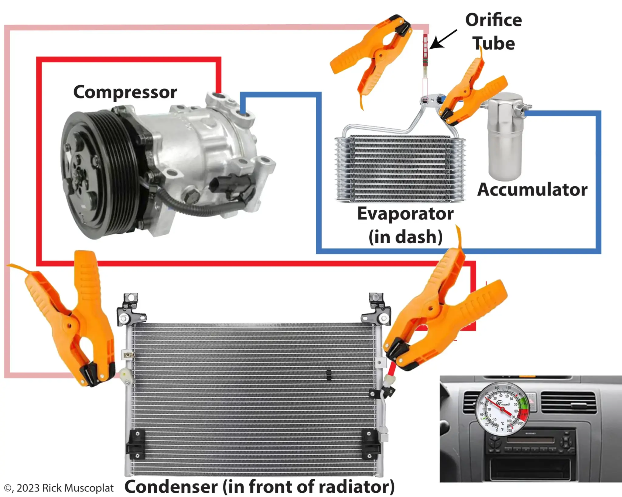
Where to place temperature probes when conducting a heat load test on an orifice tube AC system
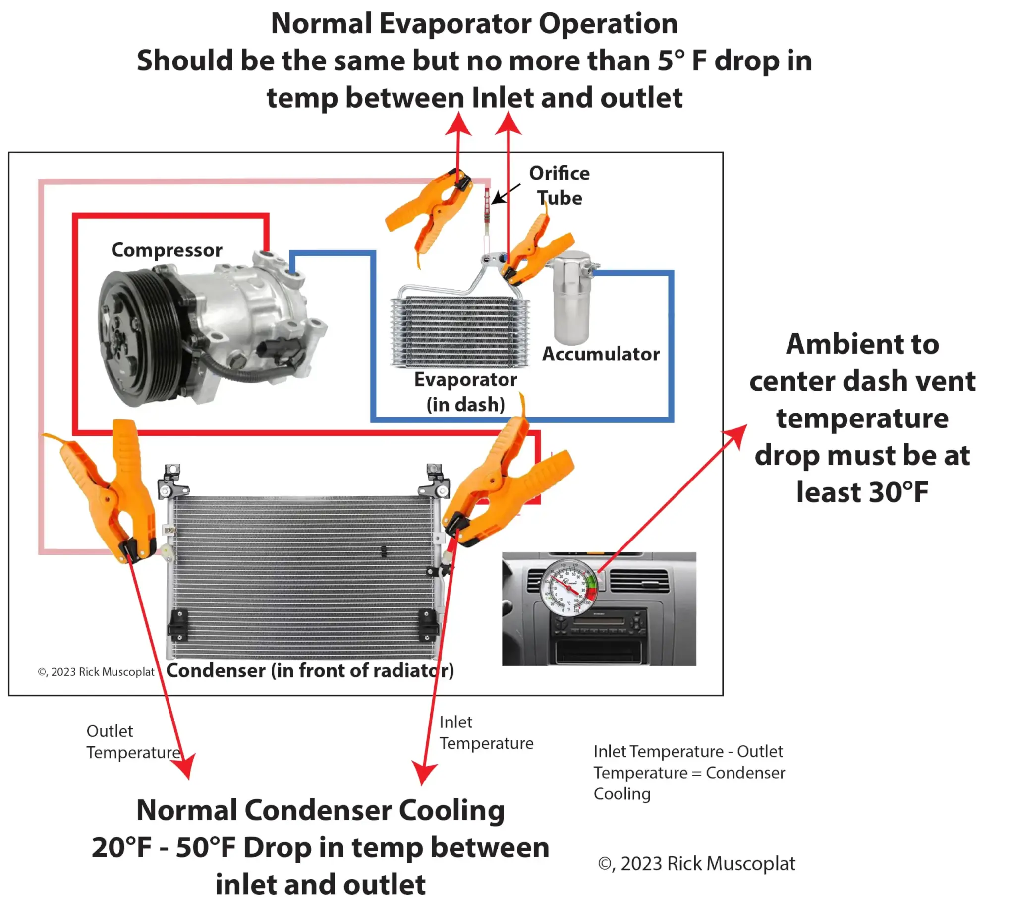
If the condenser temperature drop is out of the normal range
If the condenser inlet-to-outlet temperature is more than 50° F
• System undercharged
• Excessive air in the system
• Condenser tubes plugged
If the condenser inlet-to-outlet temperature is less than 20° F
• System is overcharged
• The condenser air fins plugged OR
• The radiator fans aren’t working properly
• There’s debris between the condenser and the radiator
If the evaporator readings are out of the normal range
If the evaporator outlet pipe is more than 5° F warmer than the inlet
• System is undercharged, and the refrigerant is picking up superheat
• Excessive oil charge
• Restricted orifice tube
If the evaporator outlet pipe is more than 5° F colder than the inlet pipe
• System overcharged
• Orifice tube O-ring not sealing
Condenser and evaporator temperatures are in the normal range, but ambient-to-vent temperatures don’t drop by 30°F
• Blend door or heater control valve not functioning properly
• Recirculation/outside air door faulty
• Evaporator internal restrictions
• Excessive oil in the system
• Air in system
• Evaporator air fins plugged
Conduct a heat load test on an expansion valve AC system
Conditions for testing
• Engine at normal operating temp and idle speed.
• Doors open.
• Set to MAX AC.
• Set the Blower to High.
• Note ambient temp and humidity.
• Place a dial thermometer in the center dash vent
• Clean the condenser, evaporator inlet, and outlet tubes using a scrubby pad to ensure good contact with the temperature probes.
• Run AC for 10-mins before measuring temperatures using the probes
NOTE: You can’t test the temperature drop between the inlet and outlet tubes on an H-block expansion valve system. There’s no room for the probes. You can only test the inlet/outlet temperatures on a capillary tube expansion valve system.
Where to place the temperature probes/clamps
Test the evaporator inlet temperature AFTER the expansion valve.
Test the temperature at the condenser at the inlet and outlet before the receiver/drier.
If the temperature difference between condenser inlet and outlet is less than 20°F here are the possible causes:
• The system is overcharged
• Poor airflow across the condenser coil.
• Debris clogging the coil fins. Clean the condenser coil.
• Improper airflow across condenser. Check for proper condenser fan operation (if electric) or fan clutch operation if a mechanical radiator fan is used.
• Check for broken or missing fan shrouds or seals
If the temperature difference between condenser inlet and outlet reading is more than 50°F here are the possible causes:
• There’s air in the system. Evacuate and pull a vacuum for at least 45 minutes.
• The system is low on charge.
• Restriction in condenser coil—sludge, too much oil, mechanical restriction due to pinched tube
©, 2023 Rick Muscoplat
Posted on by Rick Muscoplat