
How an Alternator Works In Modern Charging Systems
How an Alternator Works in Today’s Computer-Controlled Vehicles
Quick Summary
Modern charging systems are far more sophisticated than older designs and now operate as part of a computer-controlled charging system. The key things to understand are simple but important. The alternator generates electricity using a rotating magnetic field inside a stationary stator winding. The electrical output is converted from AC to DC by a rectifier and then regulated by controlling current through the rotor’s field coil. Modern vehicles often use computer-controlled smart charging, in which the engine control module adjusts the alternator output based on engine load, battery condition, and driving conditions.
Article
Understanding How an Alternator Works
Over the years, I’ve diagnosed hundreds of charging system problems, and one thing I’ve learned is that many technicians still think of alternators the way they were designed 40 years ago. But modern charging systems are far more sophisticated.
At its core, how an alternator works hasn’t changed much. The alternator converts mechanical energy from the engine into electrical energy using electromagnetism. A rotating magnetic field inside the alternator induces voltage in stationary windings, generating electrical power.
However, what has changed dramatically is how that output is controlled. Today’s alternators often work together with the vehicle’s computer to regulate voltage and manage electrical load much more precisely.
Modern systems operate as closed-loop feedback systems, constantly monitoring battery voltage and adjusting the magnetic field in the alternator to maintain proper output.
The Main Components That Explain How an Alternator Works
To fully understand how an alternator works, it helps to break the unit into its major components.
Key Components of an Alternator
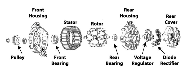
Rotor and Stator: The rotor and stator are the primary components of the alternator. Those two components are responsible for generating electricity. The rotating electromagnet rotor, also called a field coil, is positioned inside the stator, which is a stationary set of conductive wire windings. In older designs, the voltage regulator varied the amount of current into the rotor, changing the rotor’s magnetic field. As the rotor spins, the magnetic field induces an electrical current in the stator windings, providing power.
Diode Rectifier: The alternator produces alternating current (AC), but your car’s electrical system operates on direct current (DC). The diode rectifier converts the AC generated by the alternator into DC, making it usable by the vehicle’s battery and electrical systems.
Voltage Regulator: The voltage regulator is a critical component that ensures the alternator produces the correct amount of voltage and amperage. It regulates the battery’s electrical output, preventing overcharging or undercharging, which could damage the battery or reduce its life.
Cooling Fan: Alternators generate a significant amount of heat during operation, so they are equipped with an internal cooling fan to dissipate heat and prevent overheating. Some modern alternators use an external fan or are integrated with the engine’s cooling system for additional heat management.
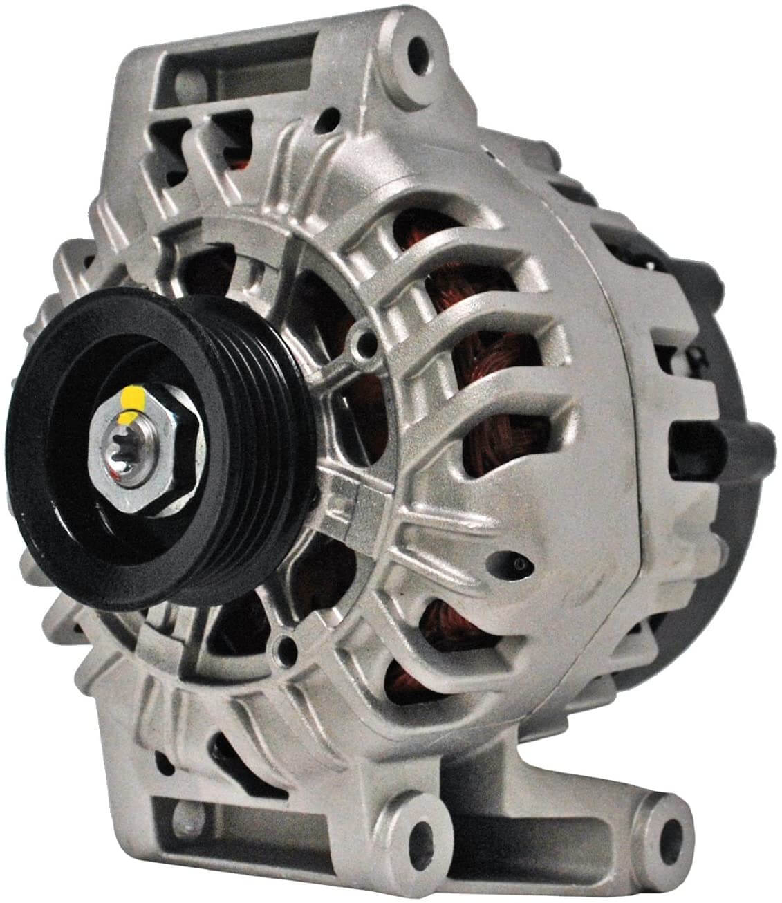
ACDelco 23119615 alternator
How does a car alternator work?
Most car alternators are driven by a belt that’s connected to the engine’s crankshaft. The voltage regulator supplies power to the rotor (field coil), turning it into an electromagnet. A series of electrical windings called a stator surrounds the rotor. As the rotor spins, the magnetic field induces current in the stator windings. That electron movement is electricity.
The rotor has a North and South pole, so as it spins, it moves electrons in one direction as the North pole passes and then in the opposite direction as the South pole passes. This is what produces alternating current (AC). Since vehicles operate on direct current, diodes (one-way electrical valves) convert AC to DC.
How The Field Coil Control Regulates Alternator Output
One of the most important concepts in understanding how an alternator works is the role of the field coil.
Contrary to what many people think, alternator output isn’t controlled by changing the alternator speed. Instead, the voltage regulation system controls output by adjusting the strength of the magnetic field inside the rotor.
This is done by switching and varying the current to the field coil according to charging needs. This is done using pulse-width modulation (PWM), where the current is pulsed on and off. The ratio of ON time to OFF time controls the strength of the field coil. The voltage regulation system can toggle the power on and off hundreds of times per second.
When the regulator increases the duty cycle—meaning the field coil is energized for longer periods—the magnetic field becomes stronger, and the alternator produces more electrical power.
When the regulator reduces the duty cycle, the magnetic field weakens, and the alternator output drops.
In other words, the entire concept behind how an alternator works is really about controlling a spinning electromagnet.
For more information on how the field coil regulates charging output, see this article.
Alternator output is directly related to engine RPM
The alternator has a smaller pulley than the crankshaft pulley, so it rotates at approximately 3 times the speed of the engine. In other words, at 2,000 engine RPM, the alternator spins at 6,000 RPM.
However, because the alternator speed is directly related to engine RPM, its output varies with engine speed. An alternator that’s rated at 140-amps can only output that rating when the engine RPM is at or above 2,000. When the engine is at idle speed (around 600 RPM), the alternator output drops to less than 40 amps.
How Modern “Smart Charging” Systems Work
If you’re diagnosing late-model vehicles, you also need to understand that how an alternator works today is often controlled by the vehicle’s computer.
Modern vehicles frequently use smart charging systems in which the engine control module (ECM) or body control module (BCM) determines the ideal charging voltage to power the vehicle and keep the battery fully charged.
These computers communicate with the alternator regulator via a Local Interconnect Network (LIN) bus. Through this system, the computer can command different charging strategies depending on driving conditions.
During heavy electrical demand—such as when the headlights, heated seats, and defroster are running—the computer may command higher alternator output.
During acceleration — the computer may reduce alternator load slightly to free up engine power and improve fuel economy.
During deceleration — the system may increase charging voltage to recover energy and recharge the battery more efficiently.
This intelligent strategy dramatically improves efficiency and battery life.
Why Load Response Control Is Important
Another important aspect of how an alternator works in modern vehicles is something called load response control.
Older vehicles often had a noticeable engine stumble when a heavy electrical load suddenly switched on. For example, when the air conditioning compressor engaged, the alternator would immediately increase output, placing extra load on the engine.
Modern regulators prevent this by gradually increasing the field current over several seconds. This allows the engine control system time to adjust idle speed and fuel delivery.
The result is smoother engine operation and improved drivability.
How the Battery Warning Light Works
Another interesting part of understanding how an alternator works is the function of the charging system warning light on the dashboard.
This light is usually controlled by the L terminal of the alternator regulator.
When the alternator is functioning normally, both sides of the warning light see the same voltage, so the light remains off. In other words, the light isn’t getting power on one side and ground on the other.
However, if the alternator fails or the drive belt breaks, the regulator system grounds the circuit, creating a voltage difference across the lamp and turning it on.
In modern vehicles with computer-controlled charging systems, the warning light may also be triggered by a diagnostic trouble code stored in the engine computer.
What causes alternator failure?
Mechanical failure
Every alternator has mechanical components: pulley, front and rear bearings, brushes, and slip rings that can wear and fail. All mechanical components are subject to wear over time. The brushes that ride on the slip rings can wear out, causing total or intermittent failure. A bearing failure can cause the rotor to contact the stator windings and destroy them.
Extreme vibration can also cause mechanical components to fail. A worn harmonic balancer or automatic belt tensioner can cause vibration in the drive belt system that transfers to the alternator bearings, accelerating wear and causing premature failure.
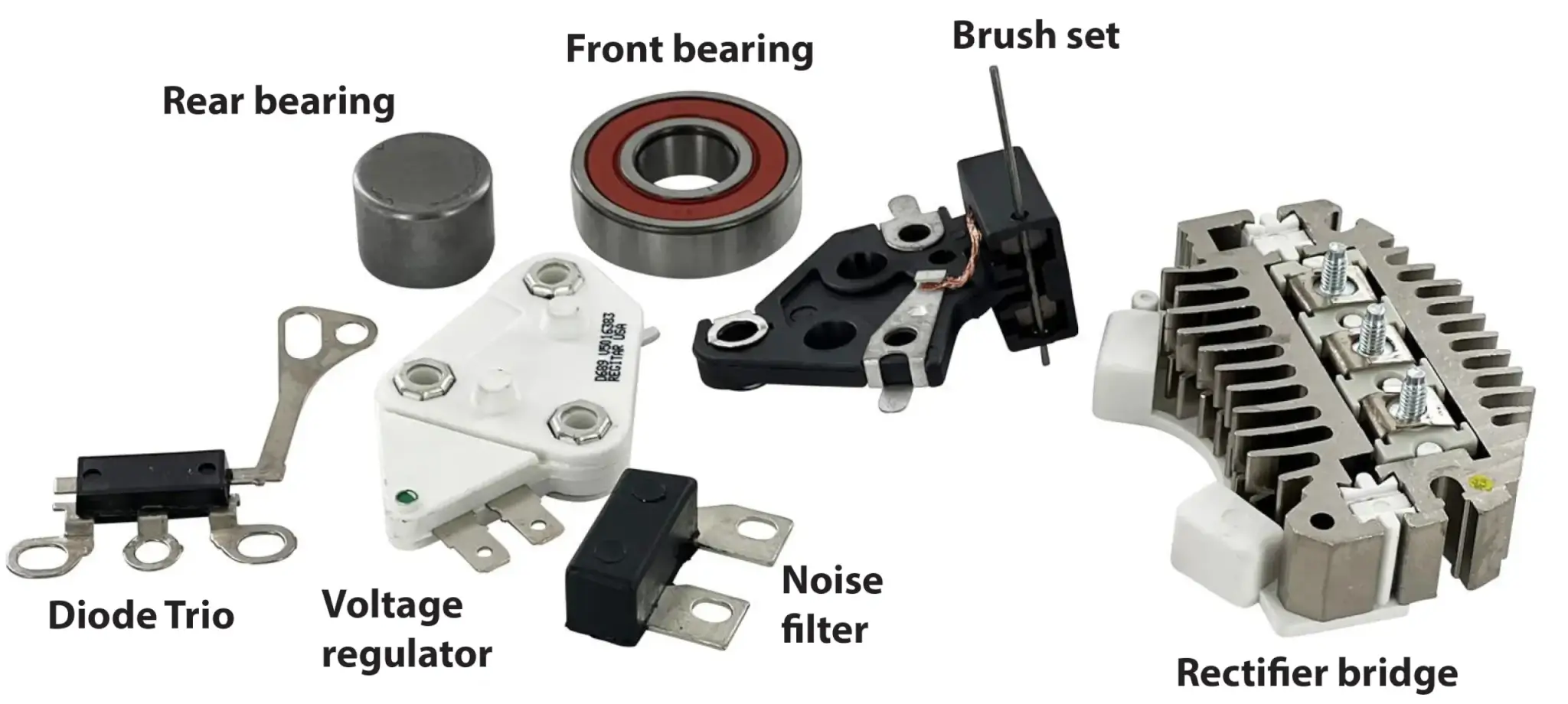
Electrical component failures are the most common cause of alternator failures
An alternator’s rotor windings, stator windings, diodes, rectifiers, and, in some cases, a voltage regulator, can fail, causing the alternator to stop producing power. The most common cause of electrical component failure is excessive heat.
What causes excessive alternator heat?
High underhood temperatures degrade insulation on the rotor and stator windings. Using your alternator to recharge a dead battery can cause excessive diode and rectifier heating, leading to premature failure.
©, 2023 Rick Muscoplat
Posted on by Rick Muscoplat