
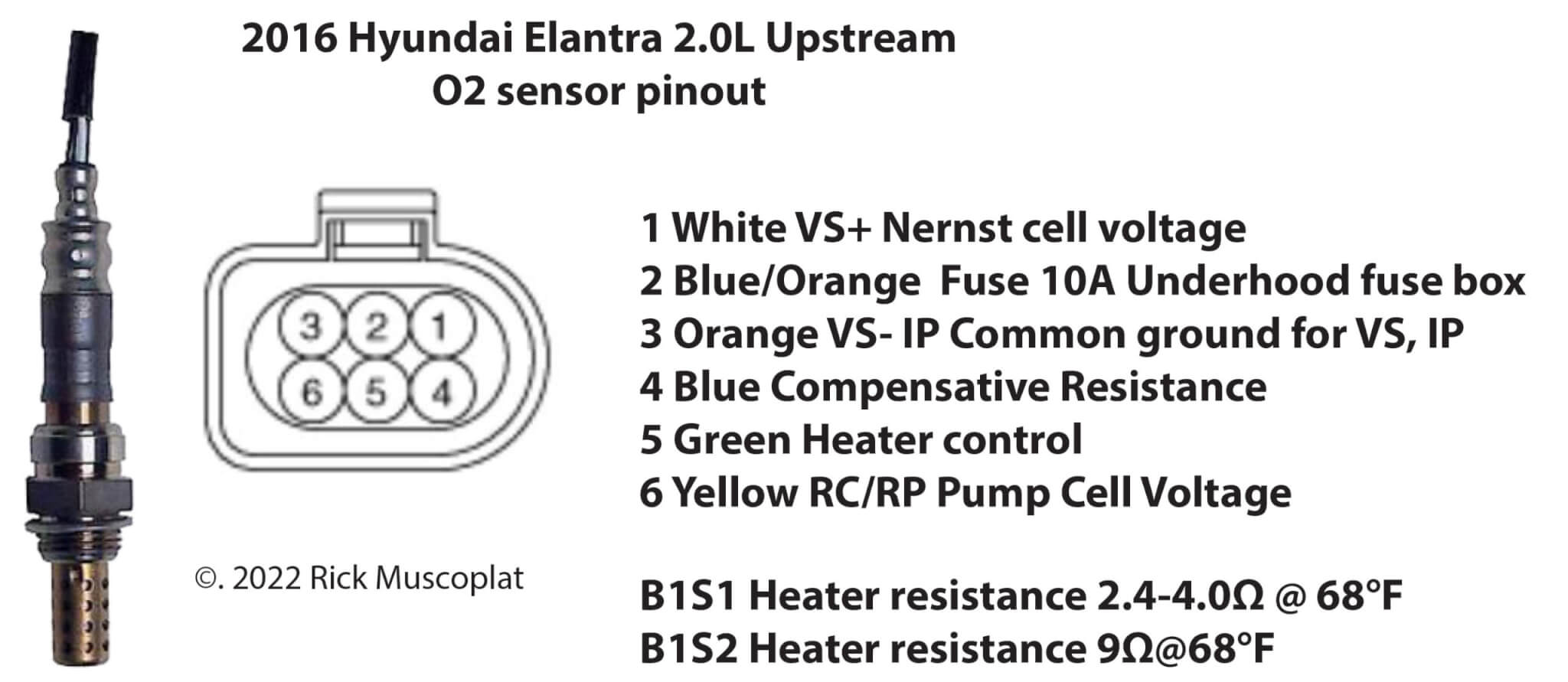
Hyundai Oxygen sensor wiring diagram
Hyundai Oxygen Sensor Wiring: Understanding Traditional vs. Wideband Sensors
Oxygen sensors provide vital data about the air-fuel mixture to the engine control unit (ECU), allowing for precise adjustments to optimize engine performance, fuel efficiency, and emissions. In this article, we’ll delve into the world of Hyundai oxygen sensor wiring, with a particular focus on the differences between traditional (narrow-band) and wideband sensors.
How a wideband O2 sensor works
Traditional oxygen sensors produce a voltage range that varies based on how much oxygen is in the exhaust stream with a low of 0-volts and a high of .9-volts and a midpoint of .45-volts. The ECM monitor the switch over the midpoint as either a rich or lean condition (above .45-volt = rich and below .45-volts = lean).
Wideband air/fuel ratio (AFR) sensors are far more sophisticated. Instead of providing a rich/lean signal, AFR sensors provide an exact voltage that varies based on the amount of oxygen in the exhaust.
The sensor is supplied with a reference or “bias” voltage and the AFR sensor produces the variance voltage from the reference voltage that’s directly proportional to the amount of oxygen in the exhaust, and it reacts in as little as 100 milliseconds.
AFR sensor construction
The AFR sensor contains a flat ceramic strip that acts as a dual sensing element that combines a “Nerst effect” oxygen pump and “diffusion gap” with the oxygen sensing element.
Exhaust gas enters the AFR sensor through vents in the metal shroud. Oxygen diffuses through the ceramic strip on the sensor element. That causes the Nerst cell to generate a voltage just like an ordinary oxygen sensor. The oxygen pump compares the change in voltage to the reference or “bias” voltage from the PCM, and balances one against the other to maintain an internal oxygen balance. This alters the current flow through the sensor, creating a positive or negative current signal that indicates the exact air/fuel ratio of the exhaust.
©, 2022 Rick Muscoplat