
The Expert’s Guide to Blower Motor Wiring Diagrams
Step-by-Step Blower Motor Diagnosis Using Wiring Diagrams
Quick Summary
If your car’s HVAC fan only works on one speed—or not at all—the problem often lies in the blower motor resistor or its wiring. In this article, I’ll explain how blower motor wiring diagrams are laid out, how the resistor controls fan speed, and how to test and fix common problems. You’ll learn exactly how power flows through the system and what to look for when diagnosing blower motor issues.
Article
How the Blower Motor Resistor Works
The blower motor resistor acts as a current and voltage limiter. It uses multiple resistance paths to reduce voltage and current, thereby controlling the motor’s speed. At lower speeds, current flows through more resistance, while at higher speeds it bypasses the resistor entirely.
How to Read Blower Motor Wiring Diagrams for Diagnosis
When using blower motor wiring diagrams for testing:
• Locate the power feed: Identify the fuse and relay supplying the circuit.
• Trace the current path: Follow the wire color codes from the relay to the blower motor and then to the resistor or control module.
• Check grounds: A poor ground connection is one of the most overlooked causes of blower motor failure.
• Look for bypass circuits: High speed usually bypasses the resistor—verify that with your diagram.
If you’re diagnosing a modern vehicle with automatic climate control, blower motor wiring diagrams will show a control module that receives commands from the climate control unit and electronically varies blower speed. The same testing principles apply, but you’ll measure control voltage or duty cycle rather than raw resistance.
Typical Blower Motor Resistor Wiring Configurations
While the exact wiring configuration may vary by vehicle make and model, there are some standard configurations.
In older vehicles, these are simple resistor packs with coiled wires. In newer models, blower motor wiring diagrams often show a solid-state module using a MOSFET transistor instead of resistors. The principle is the same, but instead of heat dissipation through coils, the module uses pulse-width modulation (PWM) to electronically regulate blower speed.
• Series Resistor Setup— In a series resistor setup, the blower motor resistor is connected in series with the blower motor. The resistor has multiple resistive elements, each corresponding to a different blower speed. The HVAC control switch selects which resistor is in the circuit, thereby determining the blower speed.

Series-wired blower motor resistor
1) Power from the battery passes through a fuse and then to the blower motor.
2) The blower motor is connected to the blower motor resistor.
3) The HVAC control switch selects the appropriate resistor in the resistor pack.
4) The selected resistor limits the current, thereby controlling the blower motor speed.
5) The circuit is completed by grounding the blower motor.
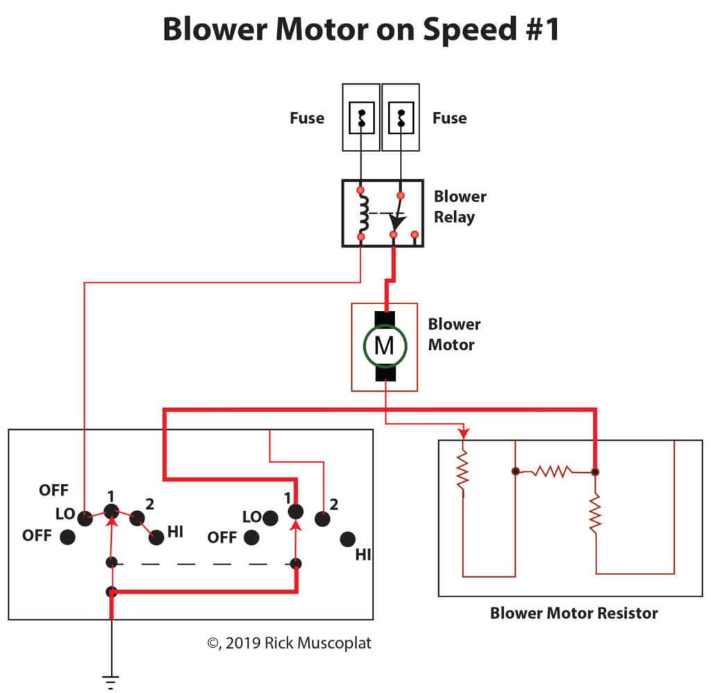
A blower motor resistor works by routing power through 1, 2, or 3 in-series resistors. See the blower motor resistor wiring diagrams below to see how it works on each speed.
Blower Motor Resistor Operation in Real-World Conditions
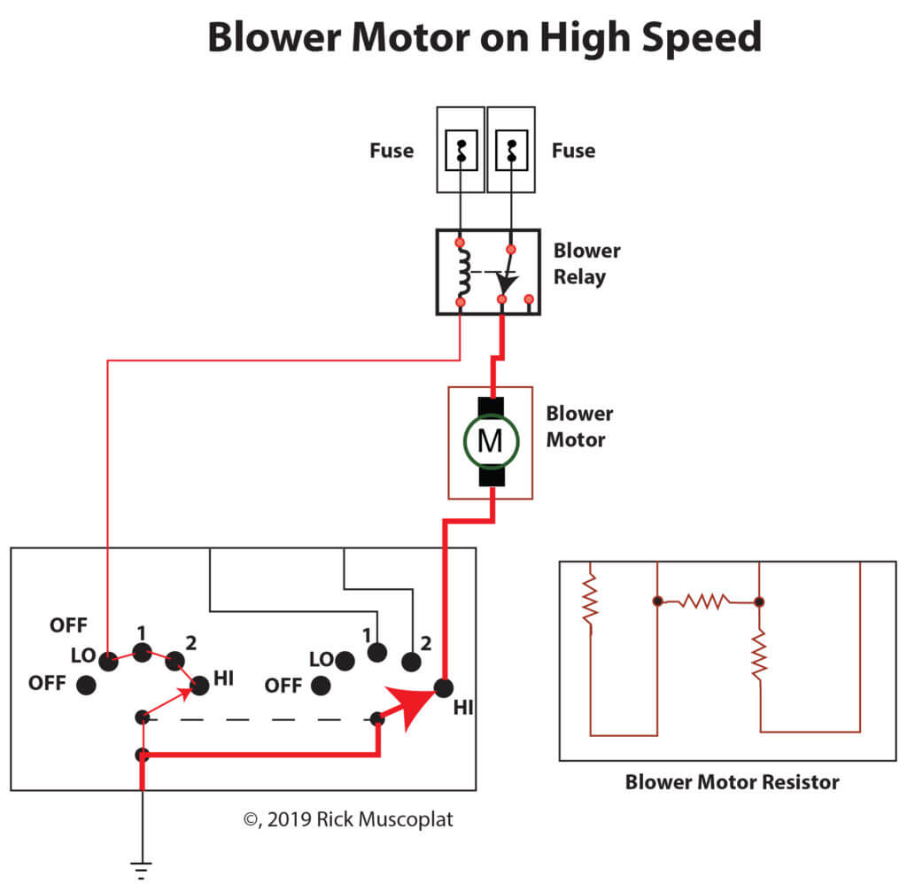
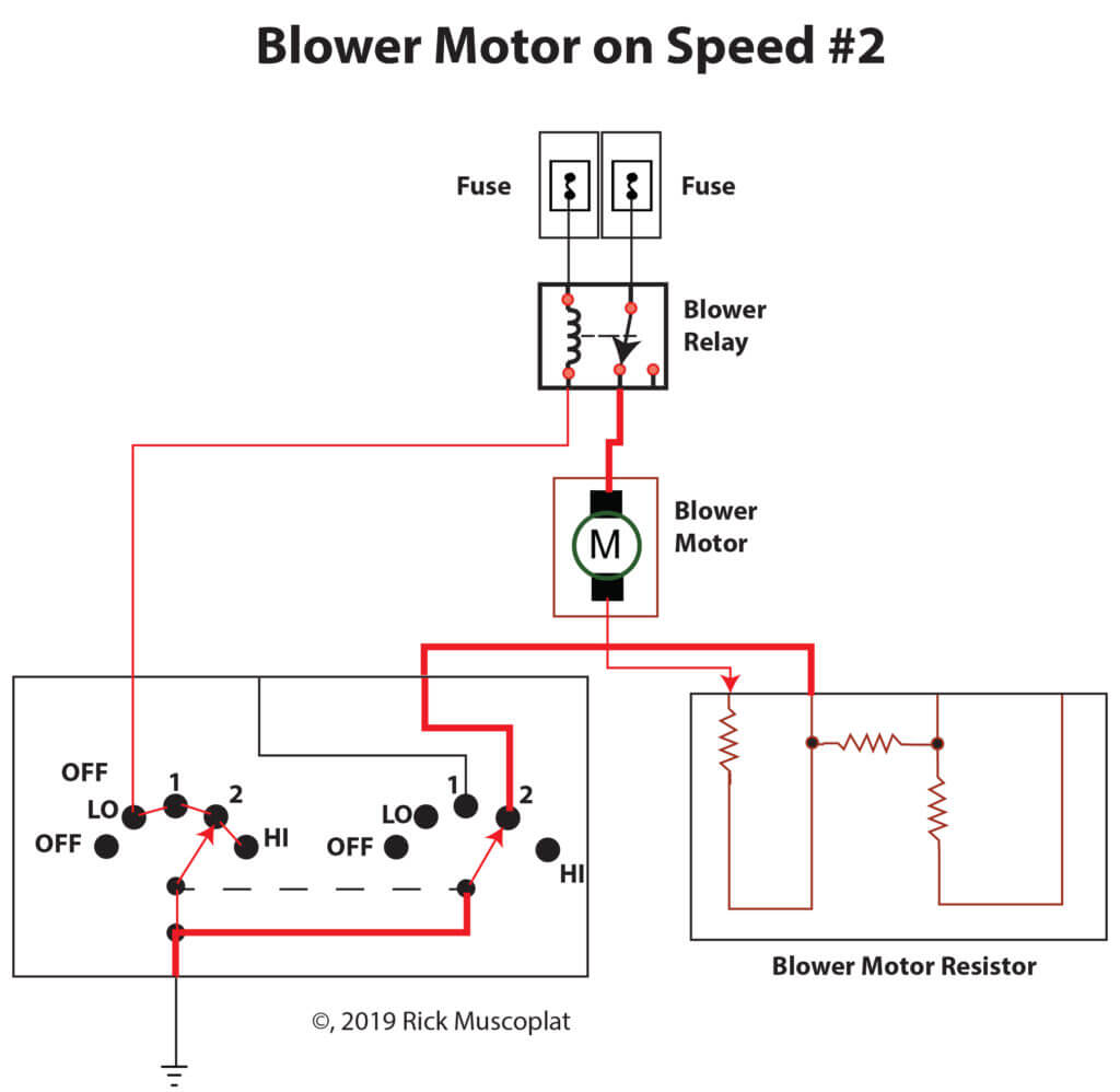
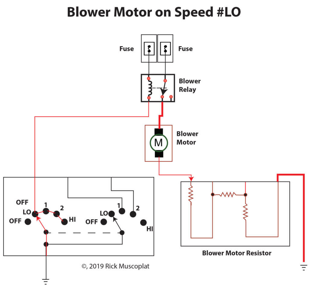
In practical terms, when you set your fan to “low,” the current flows through the full resistance of the pack. At “medium,” it flows through fewer coils, and at “high,” the resistor is bypassed, allowing full battery voltage to reach the blower motor.
This is why a failed resistor often results in a blower motor that only works on “high.” The high-speed circuit bypasses the resistor, so even if it’s burned out, the blower will still run at full blast.
If you look closely at blower motor wiring diagrams, you’ll see that a dedicated relay usually protects the high-speed circuit to handle the higher current draw.
Troubleshooting Blower Motor Problems
Blower Works Only on High
This is the most common symptom of a burned-out resistor. Use a digital multimeter to check for continuity across the resistor terminals. If one leg is open, replace the resistor pack.
Blower Doesn’t Work at All
Start by checking the fuse and blower motor relay. Then, jump power directly to the blower motor to verify it runs. If it does, the issue lies in the control circuit—often shown clearly on blower motor wiring diagrams. A bad ground or a failed control switch can also cause this symptom.
Blower Works Intermittently
Intermittent operation usually points to a corroded connector or a failing resistor. Inspect the harness for heat damage—resistors get hot, and melted connectors are common.
Blower Works at All Speeds Except One
If only one speed is missing, one of the individual resistor coils has burned out. You can verify this by measuring resistance across each leg of the resistor pack.
When to Replace the Blower Motor Resistor
You should replace the resistor if:
• The blower works only on the highest speed.
• The resistor or connector shows visible corrosion or melting.
• The fan operates intermittently even after testing the switch and motor.
Always inspect and replace any heat-damaged connectors. Many resistors now come with new pigtails because poor connections cause high resistance and heat buildup.
Final Thoughts
Understanding blower motor wiring diagrams is essential for accurate HVAC diagnosis. Whether you’re dealing with a manual resistor pack or an advanced electronic speed controller, the wiring diagram tells the full story of how current flows and where it stops.
Once you know how to read these diagrams, troubleshooting becomes straightforward—and you’ll stop guessing at what’s wrong when your car’s blower doesn’t behave as it should.
©, 2020 Rick Muscoplat
Posted on by Rick Muscoplat