
2015 Optima Fuse Box Diagram: Exploring the Fuse Boxes
2015 Optima Fuse Box Diagram: Find the correct fuse for the circuit you’re working on
In your 2015 Kia Optima, you’ve got two fuse boxes to keep track of: the Engine Compartment Fuse Box, and the Instrument Panel Fuse Box. Let’s start with the one under the hood. Just pop the hood and take a look near the driver’s side fender. That’s where you’ll find the engine compartment fuse box. It’s like the nerve center for your truck’s major systems—things like engine management, emissions, and ABS brakes are all controlled by the fuses in this box. I’ve included the 2015 Optima Fuse Box Diagrams for the engine compartment fuse box and the instrument panel fuse box.
Now, for the second fuse box, locate the trim panel on the lower portion of the dash to the left of the steering wheel. Locate the handle, pull, and lift up on the cover. You’ll find the instrument panel fuse box directly below that cover. If your electrical gadgets aren’t acting right, it might be a sign that something’s amiss with the fuses.
2015 Optima Fuse Box Diagram for the Instrument Panel Fuse Box
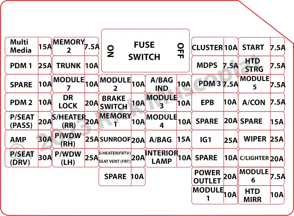
2015 Kia Optima Fuse Box Diagram for the Instrument Panel Fuse Box
| Fuse Name | Amperage | Circuits Protected |
|---|---|---|
| MULTIMEDIA | 15 | ISG LDC AUDIO,AUDIO_UVO, AUDIO(PA30A,B), NAVI1.5, NAVI_3.0, NAVI_4.0, TMU |
| PDM 1 | 25 | Smart Key Control Module (With Smart Key) |
| SPARE | 10 | — |
| PDM2 | 10 | SMK UNIT, BUTTON START SW |
| P/SEAT(PASS) | 20 | Passenger Seat Manual Switch |
| AMP | 30 | AMP |
| P/SEAT(DRV) | 30 | Driver IMS Module, Driver Seat Manual Switch, Driver Lumbar Support Switch (2WAY) |
| MEMORY 2 | 7.5 | PIC_RF_RECEIVER |
| TRUNK | 10 | Trunk Lid Relay, Trunk Room Lamp |
| MODULE 7 | 10 | SPORT_MODE_SW, RR POWER WINDOW SW |
| DR LOCK | 20 | Door Lock/Unlock Relay, Dead Lock Relay (RHD), Turn Signal Lamp Sound Relay |
| S/HEATER(RR) | 20 | Rear Seat Warmer Relay LH/RH |
| P/WDW(RH) | 25 | Driver Safety Power Window Module (RHD), Passenger Safety Power Window Module (LHD), Rear Safety Power Window Module RH, Power Window RH Relay |
| P/WDW(LH) | 25 | Driver Safety Power Window Module (LHD), Passenger Safety Power Window Module (RHD), Rear Safety Power, Window Module LH, Power Window LH Relay |
| MODULE 2 | 10 | BCM, Panorama Sunroof, Rain Sensor |
| BRAKE SWITCH | 10 | Smart Key Control Module, Start Stop Button Switch, FOB Holder, Stop Lamp Switch |
| MEMORY 1 | SEAT EXTN (IMS), DR_TRIM_EXTN (FOLD’G), CLUSTER, A/CON, ECM, AUTO FOLDING RLY, TPMS, POWER OUTLET, A_L_PHOTO_SNSR, MUT | |
| SUNROOF | 20 | Panorama Sunroof |
| S/HEATER(FRT)/SEAT VERNT(FRT) | 20 | SEAT_EXTN (HEAT/VENT) |
| SPARE | 10 | — |
| A/BAG IND | 10 | Instrument Cluster |
| MODULE 3 | 10 | Sport Mode Switch, Key Solenoid (W/O Smart Key) |
| MODULE 4 | 10 | Driver/Passenger CCS Control Module (With CCS), Driver/Passenger Seat Warmer Module (W/O CCS), Front Seat Warmer & CCS Switch, Oil Pump Inverter, ISG Low DC-DC Converter, Tire Pressure Monitoring Module |
| A/BAG | 15 | A/BAG UNIT IG1 , WCS_PASS IG1 |
| INTERIOR LAMP | 10 | Driver/Passenger Smart Key Outside Handle (With Smart Key), Driver/Passenger Door Lamp, A/C Control Module, Ignition Key ILL. & Door Warning Switch (W/O Smart Key), RF Receiver (With Smart Key), Driver IMS Module, BCM, Data Link Connector, Driver/Passenger Door Scuff Lamp, Power Outside Mirror Switch, Auto Light & Photo Sensor (W/O B/Alarm), Lamp Auto Cut Relay, Instrument Cluster |
| CLUSTER | 10 | CLUSTER (IGN1) |
| MDPS | 7.5 | Crash Pad Switch, EPS Control Module (With MDPS), Steering Angle Sensor (W/O MDPS), ATM Lever Indicator, EPB Switch, EPB Control Module |
| PDM 3 | 7.5 | Smart Key Control Module (With Smart Key) |
| EPB | 10 | EPB |
| SPARE | 20 | — |
| IG 1 | 25 | E/R BOX IG1 |
| SPARE | 10 | — |
| POWER OUTLET | 20 | Front Power Outlet |
| MODULE 1 | 10 | Auto Head Lamp Leveling Device Module (Auto HLLD), Head Lamp Leveling Device Switch (Manual HLLD), Head Lamp Leveling Device Actuator LH/RH, BCM, Front Smart Parking Assist Sensor Module, Instrument Cluster, Electro Chromic Mirror, A/C Control Module, Driver IMS Module, Rear Parking Assist Buzzer, Lane Keeping Assist Module |
| START | 7.5 | B/ALARM RLY |
| HTD STRG | 15 | Steering Wheel Heater |
| MODULE 5 | 7.5 | Smart Key Control Module (With Smart Key), Rear Seat, Warmer Relay LH/RH, E/R Fuse & Relay Box (RLY.2), Diesel Box (Fuel Filter Relay) |
| A/CON | 7.5 | A/C Control Module, E/R Fuse & Relay Box (RLY.14) |
| SPARE | 15 | — |
| WIPER | 25 | E/R BOX WIPER RLY |
| C/LIGHTER | 20 | Cigarette Lighter |
| MODULE 6 | 7.5 | PANORAMA SUNROOF (IG2), IONIZER, DSL_BOX, RR_SEAT_WARMER |
| HTD MIRR | 10 | Driver/Passenger Power Outside Mirror |
2015 Optima Fuse Box Diagram for the Underhood Fuse Box 2.0L Engine
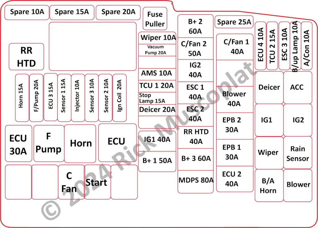
2015 Optima Fuse Bos Diagram for the Underhood Fuse Box 2.0L Engine
| Fuse Name | Amperage | Circuits Protected |
|---|---|---|
| RR HTD | — | E/R BOX RR HTD RLY COIL |
| HORN | 15 | HORN (LH, RH) |
| F/PUMP | 20 | FUEL PUMP MTR |
| ECU 3 | 15 | PCU (TGDI) BATT. DIRECT |
| SENSOR 1 | 15 | DN O2 SENSOR (TGDI), UP O2 SENSOR (TGDI), COOLING FAN RLY COIL (TGDI) |
| INJECTOR | 10 | E/R BOX F/PUMP RLY COIL |
| SENSOR 3 | 10 | CMP1, 2 (TGDI), SMATRA IMMOBILIZER |
| SENSOR 2 | 10 | CKP (TGDI), VIS (GDI), OCV1, 2 (TGDI), PCSV (TGDI), RCV (TGDI) |
| IGN COIL | 20 | ENGINE IG COIL |
| ECU 1 | 30 | ECU RLY |
| SPARE | 10 | — |
| SPARE | 15 | — |
| SPARE | 20 | — |
| WIPER | 10 | BCM, RAIN SNSR, WIPER MTR |
| VACUUM PUMP | 20 | BRAKE VACUUM PUMP IG1 |
| AMS | 10 | BATTERY SENSOR |
| TCU 1 | 20 | TCU |
| STOP LAMP | 15 | RLY.10 (HAC Relay), STOP LAMP RELAY |
| DEICER | 20 | RLY.7 (Deicer Relay) |
| IG1 | 40 | IGN SW |
| B+ 1 | 50 | B+ |
| B+ 2 | 60 | B+ |
| C/ FAN 2 | 60 | C/FAN RLY |
| IG 2 | 40 | IGN SW, IG2 RLY |
| ESC 1 | 40 | ESP UNIT MOTOR B+ , DIAGNOSIS ABS A/B VALVE B+ |
| ESC 2 | 40 | ESP UNIT SOLENOID B+ |
| RR HTD | 40 | RLY.1 (RR HTD Relay) |
| B+ 3 | 60 | B+ |
| MDPS | 80 | EPS CONTROL MODULE |
| SPARE | 25 | — |
| C/FAN 1 | 50 | COOLING FAN RLY TGDI |
| BLOWER | 40 | E/R BOX BLOWER RLY SWITCH |
| EPB 2 | 30 | EPB UNIT BATT2 |
| EPB 1 | 30 | EPB UNIT BATT1 |
| ECU 2 | 40 | EMS BOX (B+) |
| ECU 4 | 10 | ENGINE ECU |
| TCU 2 | 15 | SPEED SNSR, POSITION SW, O_P_INVERTER |
| ESC 3 | 10 | ESC UNIT IGN1 |
| B/UP LAMP | 10 | ELECTRO CHROMIC MIRROR, BCM, REAR COMBINATION LAMP (IN) LH/RH |
| A/CON | 10 | A/C CONTROL MODULE (Auto A/C) |
2015 Optima Fuse Box Diagram for the Underhood Fuse Box 2.4L Engine
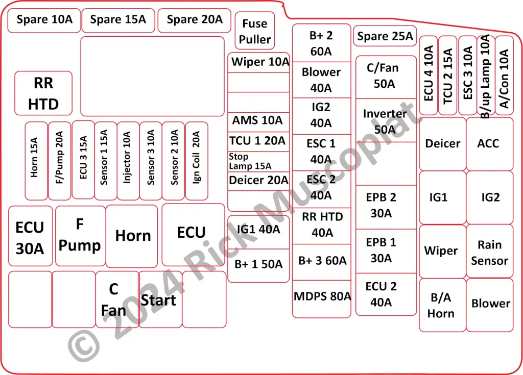
2015 Kia Optima Underhood Fuse Box Diagram
| Fuse Name | Amperage | Circuits Protected |
|---|---|---|
| RR HTD | 40 | E/R BOX RR HTD RLY COIL |
| HORN | 15 | HORN (LH, RH) |
| F/PUMP | 20 | FUEL PUMP MTR |
| ECU 3 | 15 | PCU (TGDI) BATT. DIRECT |
| SENSOR 1 | 15 | DN O2 SENSOR (TGDI), UP O2 SENSOR (TGDI), COOLING FAN RLY COIL (TGDI) |
| INJECTOR | 10 | E/R BOX F/PUMP RLY COIL |
| SENSOR 3 | 10 | CMP1, 2 (TGDI), SMATRA IMMOBILIZER |
| SENSOR 2 | 10 | CKP (TGDI), VIS (GDI), OCV1, 2 (TGDI), PCSV (TGDI), RCV (TGDI) |
| IGN COIL | 20 | ENGINE IG COIL |
| ECU 1 | 30 | ECU RLY |
| SPARE | 10 | — |
| SPARE | 15 | — |
| SPARE | 20 | — |
| WIPER | 10 | BCM, RAIN SNSR, WIPER MTR |
| AMS | 10 | BATTERY SENSOR |
| TCU 1 | 20 | TCU |
| STOP LAMP | 15 | RLY.10 (HAC Relay), STOP LAMP RELAY |
| DEICER | 20 | RLY.7 (Deicer Relay) |
| IG1 | 40 | IGN SW |
| B+ 1 | 50 | B+ |
| B+ 2 | 60 | B+ |
| BLOWER | 40 | RLY.14 (Blower Relay) |
| IG 2 | 40 | IGN SW, IG2 RLY |
| ESC 1 | 40 | ESP UNIT MOTOR B+ , DIAGNOSIS ABS A/B VALVE B+ |
| ESC 2 | 40 | ESP UNIT SOLENOID B+ |
| RR HTD | 40 | RLY.1 (RR HTD Relay) |
| B+ 3 | 60 | B+ |
| MDPS | 80 | EPS CONTROL MODULE |
| SPARE | 25 | — |
| C/FAN | 50 | E/R BOX C/FAN1 RLY SWITCH |
| INVERTER | 50 | O_P_INVERTER |
| EPB 2 | 30 | EPB UNIT BATT2 |
| EPB 1 | 30 | EPB UNIT BATT1 |
| ECU 2 | 40 | EMS BOX (B+) |
| ECU 4 | 10 | ENGINE ECU |
| TCU 2 | 15 | SPEED SNSR, POSITION SW, O_P_INVERTER |
| ESC 3 | 10 | ESC UNIT IGN1 |
| B/UP LAMP | 10 | ELECTRO CHROMIC MIRROR, BCM, REAR COMBINATION LAMP (IN) LH/RH |
| A/CON | 10 | A/C CONTROL MODULE (Auto A/C) |