
2007 Escape Fuse Diagram
2007 Escape Fuse Diagram and Mercury Mariner Fuse Diagram Battery Junction Box
This 2007 Escape Fuse Diagram and Mercury Mariner Fuse Diagram shows two fuse boxes; the Battery Junction Box located under the hood and the Smart Junction Box/Passenger Compartment Fuse Panel located on the right hand side of the center console.
There’s lots more information on this site for your vehicle.
To find fuse diagrams, click here
To find Relay locations, click here
To find Sensor Locations, click here
To find Module Locations, click here
To find Switch Locations, click here
To find Firing Order, click here
To find the most common trouble codes and fixes for your vehicle, click here
2007 Escape Fuse Diagram and Mercury Mariner Fuse Diagram for Battery Junction Box
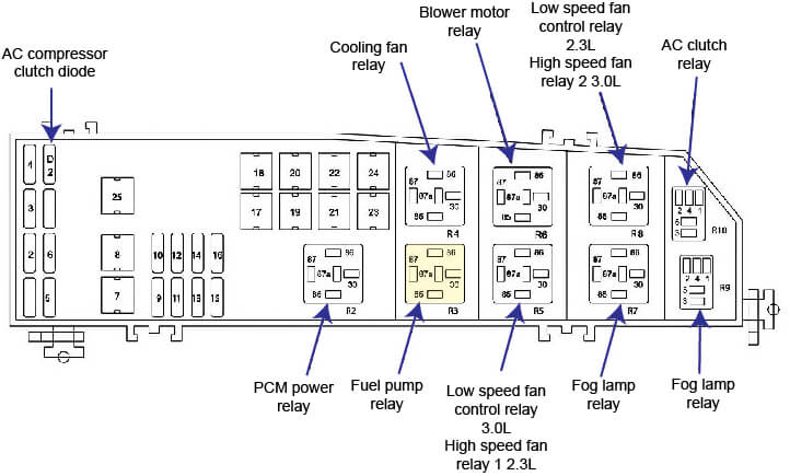
2007 Ford Escape Fuse Diagram Battery Junction Box
1 – not used
2 25A(1) Headlamp power
3 25A(1) High beams, Turn signals, Interior lamps, Headlamp power
4 5A(1) Keep Alive Power (KA PWR)
5 15A(1) Heated Exhaust Gas Oxygen (HEGO) sensors
6 20A(1) Fuel pump
7 40A(2) RUN/ACC relay – Electrochromatic inside mirror unit (17700), Cigar lighter, Front and rear wipers
8 30A(1) Powertrain Control Module (PCM) (12A650), Injectors and coil
9 15A(1) Alternator
10 30A(1) Heated seats
11 10A(1) Powertrain Control Module (PCM) (12A650), Transmission hardware unit
12 20A(1) Power point
13 20A(1) Fog lamps
14 15A(1) A/C clutch solenoid, A/C clutch relay
15 30A(1) Anti-lock Brake System (ABS) solenoid
16 25A(1) Smart junction box (RUN/START)
17 50A(2) Ignition (main)
18 40A(2) Blower motor
19 40A(2) Accessory delay relay – Subwoofer and 4X4
20 60A(2) ABS
21 40A(2) Smart junction box, horn relay
22 40A(2) Cooling Fan – 2.3L
22 50A(2) Cooling Fan – 3.0L
23 40A(2) Rear defroster, Park lamp relay
24 40A(2) High/Low speed fan – 2.3L
24 50A(2) High/Low speed fan – 3.0L
25 – Shunt
R2 – PCM power relay
R3 – Fuel pump relay
R4 – Cooling fan relay
R5 – High/Low speed fan relay 1
R7 – Starter relay
R8 – High/Low speed fan relay 2
R9 – Fog lamp relay
R10 – A/C clutch relay
D1 – not used
D2 – A/C Compressor clutch diode
(1) Mini fuse
(2) Cartridge fuse
2007 Escape Fuse Diagram and Mercury Mariner Fuse Diagram Smart Junction Box
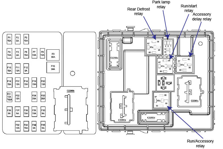
2007 Ford Escape Fuse Diagram Smart Junction Box
1 15A(1) Trailer tow park lamps
2 5A(1) not used
3 15A(1) Front and rear park lamps
4 10A(1) Ignition switch (11572)
5 2A(1) Powertrain Control Module (PCM) (12A650), Fuel pump relay, Main fan relay, High/Low speed fan relay 2, Passive Anti-theft System (PATS) transceiver
6 15A(1) High mounted stop lamp, Stop Lamps, Powertrain Control Module (PCM) (12A650), Antilock Brake System (ABS), speed control, Brake pedal position switch
7 10A(1) Instrument cluster, Diagnostic connector, Power mirror switch, audio unit
8 15A(1) Canister vent
9 30A(2) Power Door Locks, Power seats
10 15A(1) Heated mirrors
11 15A(1) Sunroof, compass, Electrochromatic inside mirror
12 5A(1) Radio
13 – not used
14 – not used
15 30A(2) Power windows
15 15A Subwoofer
17 15A(1) SJB Logic, Low beams
18 10A(1) 4X4
19 – not used
20 15A(1) Horn
21 10A(1) Rear wiper motor, Rear wiper washer
15A(1) Rear wiper motor, Rear wiper washer – Late production
22 10A(1) Instrument cluster
23 5A(1) not used
24 20A(1) Cigar lighter
25 20A(1) Front wiper motor, Front wiper washer
26 5A(1) Function selector switch assembly
27 5A(1) Deactivator switch
28 10A(1) Instrument cluster
29 10A(1) Reverse park aid
30 5A(1) not used
31 not used
32 10A(1) Overdrive switch
33 15A(1) Restraints control module, Passenger Air bag Deactivation (PAD) indicator, Occupant Classification Sensor (OCS)
34 5A(1) ABS control module, ABS test connector, speed control
35 5A(1) Heated seat module, 4X4
K1 – Run/Accessory relay
K2 – Run/start relay
K3 – Park lamp relay
K4 – Rear defrost relay
K5 Accessory delay relay
(1) Mini fuse
(2) Cartridge fuse
Posted on by Rick Muscoplat