
How to Diagnose a Throttle Body Code Like a Pro
Why You’re Getting a Throttle Body Code (And What to Do About It)
Quick Summary
Most problems come down to three areas: carbon buildup, electrical faults, or bad sensor feedback. The electronic throttle body is controlled by the ECM based on the accelerator pedal sensors, and it continuously monitors its position for accuracy. If something doesn’t match, it sets a throttle body code. My job is to determine whether the issue is mechanical, electrical, or data-related—and fix it right the first time.
When you get a throttle body code, it’s usually one of these:
• P0120 – Throttle/Pedal Position Sensor A Circuit Malfunction — The most common ETB code. The code tells you the ECM isn’t receiving a valid signal from the throttle position sensor (TPS) circuit A. For detailed information on diagnosing and fixing a P0120 code, see this post.
• P0121 – TPS Circuit Range/Performance — The TPS signal is out of the expected range — often caused by a dirty or worn throttle body. For detailed information on diagnosing and fixing a P0120 code, see this post.
• P0122 – TPS Circuit Low Input — The signal voltage is too low, usually caused by a wiring, connector, or sensor failure. For detailed information on diagnosing and fixing a P0120 code, see this post.
• P0123 – TPS Circuit High Input — The signal voltage is too high, similar to P0122. For detailed information on diagnosing and fixing a P0120 code, see this post.
• P0124 – TPS Circuit Intermittent — Erratic or unstable TPS signal, often a loose connector or failing sensor. For detailed information on diagnosing and fixing a P0120 code, see this post.
How the Electronic Throttle Body Really Works
Modern vehicles don’t use a throttle
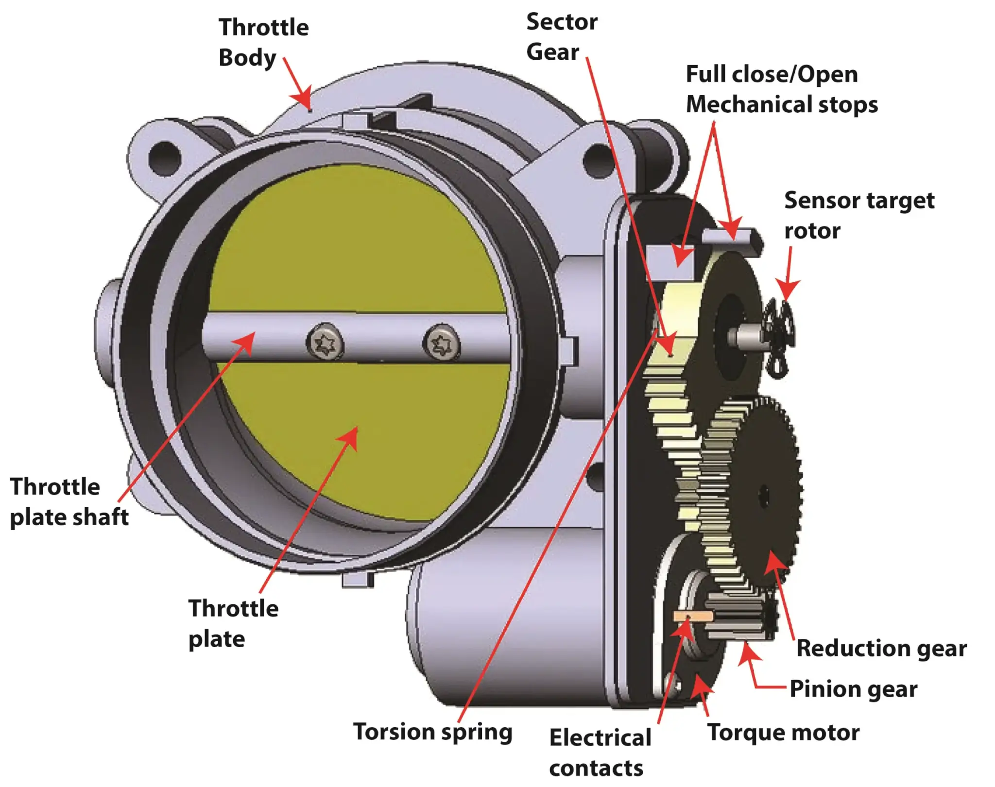
The inside of an electronic throttle body
cable anymore. Instead, they rely on an electronic throttle control system, where the accelerator pedal sends a signal to the ECM. Based on that signal—and other inputs like engine load and temperature—the ECM commands a small DC motor inside the throttle body to open or close the throttle plate.
Inside that throttle body, there’s more going on than most people realize. There’s a precision gear reduction set that allows extremely fine control of airflow—sometimes adjusting the plate by fractions of a degree. Then, just as important, there are dual throttle position sensors that send feedback to the ECM so it knows the plate moved exactly as commanded.
If that feedback doesn’t match the command, the ECM flags it—and that’s when you get a throttle body code.
Step 1: Always Start With the Scan Tool
That’s a critical step a lot of people miss. A pending throttle body code won’t turn on the check engine light yet, but it’s often the first clue something is starting to fail.
Once I find a code, I don’t jump to conclusions. I look at freeze frame data, throttle angle readings, and compare commanded vs. actual throttle position. That tells me whether I’m dealing with a mechanical restriction or an electrical problem.
Step 2: Visual Inspection—Where Most Problems Are Found
After scanning, I move straight to a visual inspection. I remove the intake duct and look inside the throttle body.
Here’s something I’ve seen countless times: carbon buildup around the throttle plate. Over time, deposits restrict airflow, and the ECM tries to compensate—but it can only do so much. Eventually, airflow becomes inconsistent enough to trigger a throttle body code.
If I see buildup, I clean it—but I also warn customers that cleaning alone may not fix everything. Once airflow changes, the ECM may need to relearn the new baseline idle position.
Step 3: Testing the Throttle Body Motor
The ECM controls the throttle body motor using a pulse-width modulated (PWM) signal. I prefer using a lab scope here instead of a multimeter because I want to see the waveform—not just voltage.
I connect to the motor circuits and watch what happens as I press the accelerator. A healthy system will show a clean, consistent PWM signal and smooth motor response.
At the same time, I listen carefully. A noisy or erratic motor is a red flag. If I hear grinding or hesitation, I’m already leaning toward a failing throttle body.
And one important rule I always follow: never try to move the throttle plate by hand with the key on. That can damage the motor—and your fingers.
Step 4: Verify Accelerator Pedal Input
The throttle body doesn’t operate on its own—it responds to the accelerator pedal position sensor. If that sensor sends erratic signals, the ECM will command the throttle body incorrectly, and you’ll get a throttle body code even though the throttle body itself is fine.
So I always check pedal sensor data on the scan tool or scope. The signal should rise and fall smoothly. Any glitches or dropouts point to a pedal sensor issue, not a throttle body failure.
Step 5: Test Throttle Position Sensor Feedback
These sensors provide feedback to the ECM, confirming the throttle plate’s actual position. I monitor their voltage signals while the throttle moves.
What I’m looking for is a smooth, linear voltage change. If I see spikes, dropouts, or flat spots, that tells me the sensor is failing—and since most are integrated, that means replacing the entire throttle body assembly.
Step 6: When to Replace the Throttle Body
I only replace a throttle body after I’ve proven it’s defective. That means:
• The motor isn’t responding correctly
• The position sensors show erratic signals
• All inputs (like pedal sensors) are verified good
When I do replace one, I stick with OE-quality parts. Cheap aftermarket units can cause repeat failures, poor idle, or even new throttle body codes.
Step 7: Don’t Skip the Idle Relearn Procedure
After cleaning or replacing a throttle body, the ECM needs to relearn the correct idle position. If you skip this step, you may end up with a rough idle, stalling, or another throttle body code.
The relearn process varies by vehicle, but it often involves bringing the engine to operating temperature, cycling the ignition, and letting the ECM recalibrate under controlled conditions.
©, 2026 Rick Muscoplat
Posted on by Rick Muscoplat