
How to test a relay using a multi-meter
The Complete Guide to Test a Relay With a Multimeter
Quick Summary
Test a relay in just a few minutes by checking three things: the relay coil resistance, the contact operation, and the voltage transfer through the relay. If those tests pass, I know the relay is good, and the problem lies elsewhere in the circuit.
Article
How to Test a Relay With a Multimeter (Step-by-Step Guide From a Pro)
Over the years, I’ve diagnosed thousands of electrical problems in cars and trucks. One of the simplest yet most important skills any technician can learn is how to test a relay. When something like a fuel pump, radiator fan, horn, or headlights suddenly stops working, the relay controlling that circuit is often the first suspect.
Relays are used because they allow a low-current control signal to switch a high-current device. In other words, the vehicle computer or a small dashboard switch can safely control large electrical loads without running heavy wiring throughout the vehicle. Because of this design, learning to properly test a relay can quickly tell you whether the problem is the relay itself or something else in the electrical system.
The good news is that you don’t need expensive diagnostic equipment. A simple digital multimeter and a couple of jumper wires are all you need to test a relay like a professional.
What tools do you need to test a relay
• A digital multimeter
• Jumper wires with a clamp on one end and a test probe on the other
Understanding How an Automotive Relay Works
Every relay contains two basic components:
1) A control coil – This is an electromagnet. When voltage is applied, it creates a magnetic field.
2) The switch contacts – These are the metal contacts that open or close the circuit.
When current flows through the coil, the magnetic field pulls a small metal armature, closing the electrical contacts. When power is removed, a spring reopens the contacts.
This allows a small control current to operate a much larger electrical load. That design reduces wiring size, cuts vehicle weight, and allows computers to safely control high-amperage circuits.
Understanding this basic operation makes it much easier to test a relay because you’re really just testing two things:
• Whether the coil works
• Whether the contacts open and close correctly
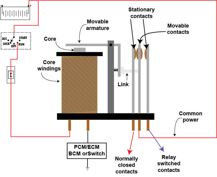
In this configuration, battery power is supplied to the control coil whenever the key is turned. The PCM/ECM controls when the ground side of the circuit is completed. Once the ground is provided, the control coil energizes, moving the armature, link, and electrical contacts.
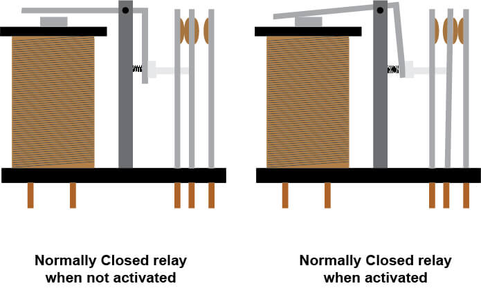
On the left, you see a normally closed relay. When there’s no power to the control coil, the left two contacts are touching, completing the circuit. However, when power is applied and the control coil is energized, the armature and linkage move the contacts apart, breaking the circuit.
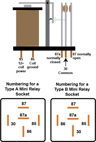
Before you can test a relay, you have to understand the relay numbering system
Most car makers use a mini relay for high-current applications and a  micro relay for low-current applications. The terminal numbering systems differ between the two, and knowing which socket terminals go to the control coil and control coil ground, and which are the switched terminals, is critical to diagnosing your problem.
Car makers use two models of the mini relay—Type A and Type B.
The relay’s internal components are the same, but the terminal placement differs slightly between types A and B.
Car makers use MICRO relays for low-current applications
The numbering system for micro relays is different.
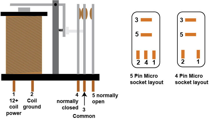
Micro relay numbering and socket layout
What goes bad on a relay?
Relay contact can pit and stick closed, causing a motor to run constantly. The easiest way to determine if the relay contacts are stuck is to tap the relay with the handle of a screwdriver. The vibration usually causes the contacts to open. If the relay opens with the tap, there’s no need to test it. It’s bad. Replace it.
The relay control coil can develop an internal short to ground, causing the fuse to blow every time the control coil gets power. The easiest test for that situation is to remove the relay and replace it with another relay from the fuse box. The relay must have the same terminal layout. If the swapped relay doesn’t blow the fuse, it’s obvious the first relay was shorted to ground.
The relay coil can also develop an open condition. When that happens, the relay can’t develop a proper magnetic field and can’t close the relay contacts. The easiest way to test for an open condition is to set your meter on the OHMS reading and place the two test probes on the 85 & 86 terminals of the mini relay or the 1 & 2 terminals of a micro relay.
Step 1: Locate and Remove the Relay
Most automotive relays are located inside the vehicle’s fuse box. Some are in the engine compartment fuse panel, while others are inside the cabin. In certain cases, manufacturers mount relays separately under the hood or near the component they control.
Once I locate the relay, I carefully pull it out of its socket. I always inspect the terminals before doing any electrical testing. Corrosion, dirt, or heat damage can cause poor connections that mimic a bad relay.
If the terminals look dirty, I clean them with electrical contact cleaner before I proceed.
Sometimes I’ll also swap the suspected relay with an identical one from another circuit just as a quick check. But if I really want to know for sure, I’ll properly test a relay using my multimeter.
Step 2: Test the Relay Coil Resistance
Most automotive relays use terminal numbers:
85 and 86 – Relay coil
30 and 87 – Switching contacts
I set my multimeter to the Ohms (Ω) setting and place the test leads on terminals 85 and 86. A healthy relay coil usually measures somewhere between 50 and 120 ohms.
If the meter reads OL (open circuit) or infinite resistance, the coil is broken, and the relay is bad. If the resistance is extremely low, that indicates a shorted coil that can blow a fuse.
Either way, if the coil fails this test, there’s no reason to go any further. The relay needs to be replaced.

Relay terminal numbering
Step 3: Test the Relay Contacts
Leave the multimeter set to continuity or resistance and place the probes on terminals 30 and 87.
When I test a relay in this condition (with no power applied to the coil), a normal, normally-open relay should show no continuity. That means the circuit is open, which is exactly what I expect.
If the meter shows continuity at this stage, the contacts are stuck closed, and the relay is defective
Step 4: Energize the Relay and Listen for the Click
Using jumper wires, I apply 12 volts to terminal 86 and ground terminal 85.
When I test a relay this way, a healthy relay will produce a distinct click. That click is the sound of the electromagnet pulling the armature and closing the contacts.
If I don’t hear a click, I cycle the power a few times to confirm. No click usually means the relay coil has failed or the internal mechanism is stuck.
Step 5: Verify Power Transfer Through the Relay
With the relay energized, I connect battery power to terminal 30. Then I check terminal 87 with the multimeter set to DC volts. If the relay is functioning properly, I should see battery voltage at terminal 87. When I remove power from the coil, the voltage should drop to zero immediately. This confirms the relay is switching power exactly the way it should.
A Quick Trick I Use Before Testing
Before I go through the full process to test a relay, I sometimes try a quick diagnostic trick.
I lightly tap the relay with the screwdriver handle while the circuit is energized. If the relay contacts are sticking, the vibration can momentarily free them.
If the component suddenly starts working after the tap, I already know the relay is faulty and should be replaced.
Final Thoughts From the Shop
In my experience, learning how to test a relay is one of the most useful electrical diagnostic skills any technician or DIY mechanic can have. A relay failure can mimic many other problems, from bad wiring to failed sensors or even defective control modules.
But once you know how to test a relay with a multimeter, you can eliminate that possibility quickly and move on with your diagnosis.
The entire process usually takes less than five minutes. And in many cases, confirming that a relay is bad can save hours of unnecessary troubleshooting.
©, 2018 Rick Muscoplat
Posted on by Rick Muscoplat