
The Role of Crankshaft Position Sensors in Engine Performance
Crankshaft Position Sensors: How They Work and Why They Matter
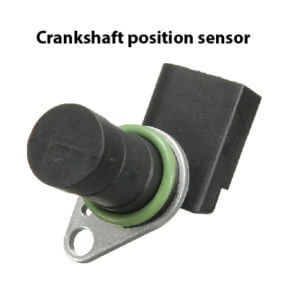
A crankshaft sensor, also known as a crankshaft position sensor (CKP sensor), is an electronic device used in internal combustion engines to monitor the position and rotational speed of the crankshaft. This information is crucial for the engine control unit (ECU) to manage engine functions such as fuel injection, ignition timing, and other vital operations. The crankshaft sensor plays a key role in ensuring the efficient and smooth operation of the engine.
Its Purpose and Function
• Position Detection— The CKP sensor detects the exact position of the crankshaft, which is necessary to determine the pistons’ positions within the cylinders. This information is critical for the precise timing of fuel injection and spark ignition.
• Engine Speed Measurement— The sensor measures the rotational speed (RPM) of the crankshaft, which is used by the ECU to adjust various engine parameters for optimal performance, efficiency, and emissions control.
• Synchronization with Camshaft Sensor— The data from the crankshaft sensor is often used in conjunction with the camshaft position sensor to determine the exact timing for fuel injection and ignition events. This synchronization is particularly important in engines with variable valve timing and direct injection systems.
• Misfire detection— Every time a spark plug fires, the engine rotation speed increases. The ECM expects to see that increase in speed from the crankshaft sensor. However, if a cylinder misfires, the crankshaft doesn’t increase. If the ECM sees a pattern of no increase after spark plug events in a specific cylinder, it concludes that the cylinder has misfired. The CKP is critical in reporting the lack of speed increase to the ECM.
Types of Crankshaft Position Sensors
Hall Effect Sensors: These sensors use a magnetic field and a semiconductor to detect the crankshaft’s position. A magnet or reluctor wheel with teeth attached to the crankshaft disrupts the magnetic field, generating an electrical signal that the ECU interprets to determine the crankshaft’s
position and speed.
Magnetic (Variable Reluctance) Sensors: These sensors generate an electrical signal based on the changes in the magnetic field as a reluctor wheel or tone wheel with teeth passes by the se
nsor. The signal is typically in the form of a sine wave or pulse train, which the ECU uses to calculate the crankshaft’s position and speed.
Optical Sensors: Less commonly used, optical sensors employ a light source and a photodetector to measure the crankshaft’s position. As the crankshaft rotates, it interrupts the light beam, producing a signal that indicates the crankshaft’s position.
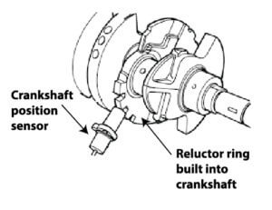
The CKP sits in close relation with the reluctor ring built into the crankshaft
The reluctor ring gap is used to recognize the beginning of a new rotation
A Hall Effect sensor contains a thin metal strip with a current applied to it. When a magnetic field passes in front of the sensor, the electrons are deflected toward one edge of the metal strip, producing a voltage gradient across the short side of the strip (perpendicular to the feed current). The voltage change is detected and translated into a digital signal that’s sent to the PCM to determine fuel injection or spark timing.
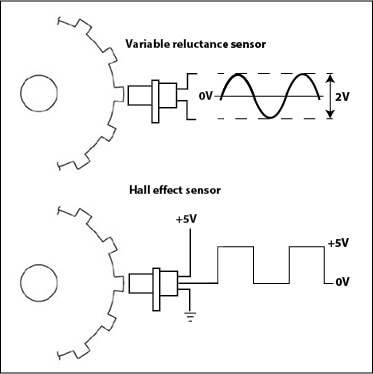
2 types of crankshaft sensors: Variable reluctance and Hall Effect
The PCM uses input from both the crankshaft sensor and the camshaft sensor to determine the fuel injector and spark timing.
What does a crankshaft sensor do?
A crankshaft sensor is used on a fuel injected engine to inform the powertrain control module (PCM) the exact of the crankshaft so the computer can operate the fuel injectors and spark plugs at the proper moment.
Where is the crankshaft sensor located?
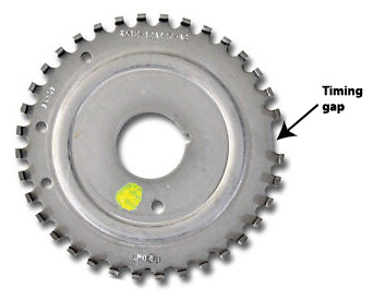
The notched wheel can be mounted on the front of the crankshaft near the harmonic balancer, on the flywheel (manual transmission) or flex plate (automatic transmission), or right on the crankshaft itself. The notched wheel (also called a “reluctor ring” or “tone ring”) has evenly spaced teeth and a timing gap. As the tone ring rotates, the crankshaft sensor senses each notch and reports the movement to the PCM. That’s how the PCM determines the number of degrees of crankshaft movement AND the rate of rotation speed of the crankshaft. The timing gap helps the computer determine when a full revolution has occurred.
Symptoms of a Faulty Crankshaft Position Sensor
• Check Engine Light— A malfunctioning CKP sensor can trigger the check engine light on the dashboard.
• Engine Misfires— Incorrect information from the CKP sensor can cause the engine to misfire, as the timing of fuel injection and ignition may be off.
• Starting Problems— A faulty sensor can cause difficulties in starting the engine or prevent it from starting altogether.
• Poor Engine Performance— Symptoms may include rough idling, reduced power, hesitation during acceleration, and decreased fuel efficiency.
How to test a crank sensor?
A VR type sensor can be tested using a digital voltmeter set to the AC scale. Connect the meter and crank the engine. You should see an AC voltage. However, this only tests the sensor’s ability to generate an AC voltage. The meter can’t measure amplitude and frequency. For that, you need a digital oscilloscope.
A Hall Effect sensor can only be tested with a digital oscilloscope.
Crankshaft sensor replacement cost
A crank sensor usually costs less than $100, and the labor to replace the sensor usually is less than one-half hour. However, the cost to diagnose the failure can easily run upwards of $150, making the total repair cost around $300-$400.
©, 2018 Rick Muscoplat
Posted on by Rick Muscoplat