
Understanding the Role of Tone Rings in Automotive Technology
Exploring the Function of Tone Rings in Vehicle Components
A tone ring, also known as a reluctor ring or an encoder wheel, is a component used in various automotive systems to monitor the rotational speed or position of a rotating component, such as a wheel, crankshaft, or camshaft. It works in conjunction with a sensor to provide data for systems like Anti-lock Braking Systems (ABS), traction control, and engine control units (ECUs).
Where are tone rings used?
• Brake system— To monitor wheel speed for the ABS and Stability Control systems
• Fuel delivery and Ignitions systems— To monitor the speed and location of the shafts to determine when to fire fuel injectors and spark.
It can be used in an engine to help the computer determine the exact location of the crankshaft and camshaft. In those cases, the ring will have a timing notch that’s used to indicate that the shaft has completed a full revolution.

This is one version of a tone wheel. Notice the gap that tells the computer when it has completed a full revolution
They can also used in anti-lock brake systems (ABS) to detect wheel rotation rate. ABS systems do not need to know the exact location of the shaft, just the speed of rotation, so there are no notches on an ABS tone ring.
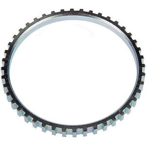
Tone ring for ABS brakes. No notches or gaps
Tone/reluctor rings can be internal or external
Crankshaft and camshaft rings can be located on the end of the shaft and exposed to external elements or contained inside the engine.
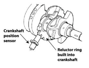
The reluctor ring is built into the crankshaft and operates inside the engine.
ABS rings can be mounted on the drive shaft, in the wheel hub or inside the wheel bearing

Tone ring mounted on the harmonic balancer at the the front of the engine and exposed to the elements
The sensor can be active or passive
Passive sensor
A passive sensor consists of a coil of wire wrapped around a magnet. The wiring harness has 2-conductors: one for a reference voltage and another for ground to the coil wrapped around the magnetic core. It is placed in close proximity to the tone wheel. As the steel or iron tone ring
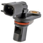
Wheel speed sensor
rotates past the sensor, each tooth on the tone ring disturbs the magnetic field while also generating an A/C voltage in the coil. The voltage increases as the tooth approaches the magnet and drops to zero as the tooth aligns directly with the magnet. Then, as the tooth passes the magnet, it induces a negative voltage in the magnetic coil. A passive sensor can be tested with a DVOM meter for resistance and AC voltage
Active sensors
An active sensor still detects the movement of a magnet by either blocking the magnetic field with a rotating vane style tone ring or by detecting the change in North/South poles of the magnet. These sensors don’t generate voltage like passive sensors. Instead they require power to the semiconductor chips and report either a digital or analog signal.

An active wheel speed sensor requires power and reads a multipole magnetic ring