
2004 Explorer Fuse Box Diagram: Exploring the Fuse Boxes
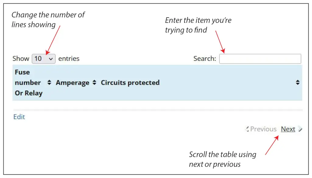
2004 Explorer Fuse Box Diagram: Find the correct fuse for the circuit
This 2004 Explorer Fuse Box Diagram shows two primary fuse boxes: the Power Distribution Box (located in the engine bay) and the Passenger Compartment Fuse Fuse Panel. The fuse panel is located below the instrument panel on the driver’s side. Here’s what you need to know about each of them.
The power distribution box is located in the engine compartment near the firewall and next to the brake master cylinder. The power distribution box contains high-current fuses that protect your vehicle’s main electrical systems from overloads.
Find the most commonly replaced fuses here
Passenger Compartment Fuse Box
2 20A Moonroof
24 15A Cigar lighter
Power Distribution Center Under the Hood
#4 30A Rear defrost
#7 20A Power point #2
#9 20A Power point #1
#21 30A Front wiper motor
#26 20A Fuel pump
#30 20A Rear wiper motor
#36 40A Blower motor
#42 10A Right low beam
#43 10A Left low beam
#46 20A High beams
2004 Explorer Fuse Box Diagram for the UnderHood Fuse Box/Power Distribution Box
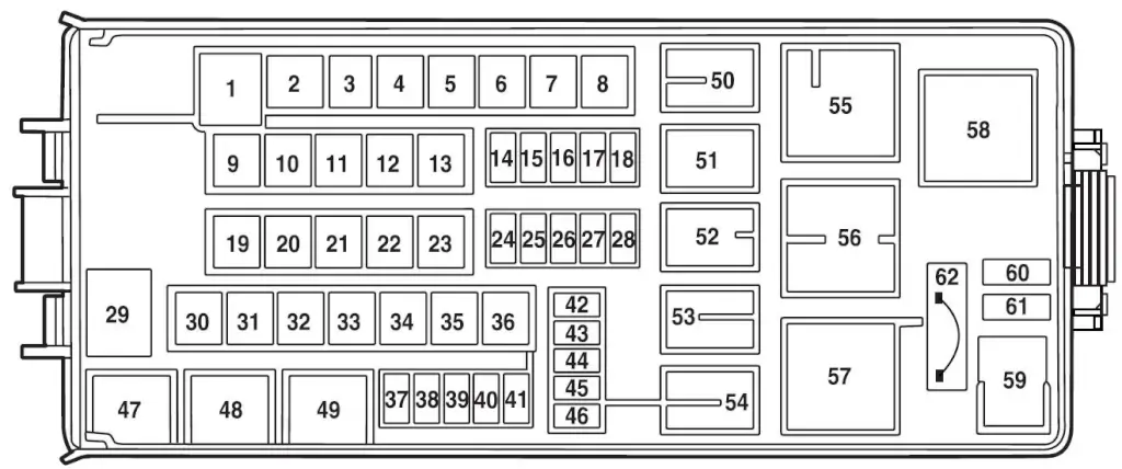
| Fuse Number | Amperage | Circuits Protected |
|---|---|---|
| F1 | 60 | PJB #1 Passenger Junction Box |
| F2 | 30 | BSM |
| F3 | — | Not used |
| F4 | 30 | Rear defrost |
| F5 | 40 | Anti-lock Brake System (ABS) pump |
| F6 | 60 | Delayed accessory, Power windows, Audio |
| F7 | 20 | Power point #2 |
| F8 | 30 | 4x4 shift motor |
| F9 | 20 | Power point #1 |
| F10 | 30 | ABS module (valves) |
| F11 | 40 | Powertrain Control Module (PCM) |
| F12 | 50 | Ignition relay, Starter relay |
| F13 | 40 | Trailer tow battery charge, Trailer tow turn signals |
| F14 | 10 | Daytime Running Lamps (DRL) (Canada) |
| F15 | 15 | Memory (PCM/DEATC/Cluster), Courtesy lamps |
| F16 | 15 | Park lamps, Autolamp parklamps, Front foglamps relay coil |
| F17 | 5 | Two-speed 4x4 (relay coils) |
| F18 | 20 | PCM with two-speed 4x4 clutch |
| F19 | 20 | High beam relay |
| F20 | 30 | Trailer electric brake module |
| F21 | 30 | Front wiper motor |
| F22 | 20 | Low beam, Autolamp |
| F23 | 30 | Ignition switch, PCM diode |
| F24 | — | Not used |
| F25 | 15 | Brake on-off |
| F26 | 20 | Fuel pump |
| F27 | 20 | Trailer tow park lamps, Trailer tow back-up |
| F28 | 20 | Horn relay |
| F29 | 60 | PJB #2 |
| F30 | 20 | Rear wiper motor |
| F31 | — | Not used |
| F32 | — | Not used |
| F33 | 30 | Auxiliary blower motor |
| F34 | 30 | Passenger power seat, Adjustable pedals (non-memory) |
| F35 | — | Not used |
| F36 | 40 | Blower motor |
| F37 | 15 | A/C clutch relay, Transmission |
| F38 | 15 | HEGO, VMV, CMS, ESM, CVS |
| F39 | 15 | Injectors, Fuel pump relay coil |
| F40 | 15 | PCM power |
| F41 | 15 | Coil on plug (4.6L engine only), Ignition coil (4.0L engine only) |
| F42 | 10 | Right low beam |
| F43 | 10 | Left low beam |
| F44 | 15 | Front foglamps |
| F45 | 2 | Brake pressure switch (non-AdvanceTrac vehicles) |
| F46 | 20 | High beams |
| F47 | Relay | Horn relay |
| F48 | Relay | Fuel pump relay |
| F49 | Relay | High beam relay |
| F50 | Relay | Front foglamps relay |
| F51 | Relay | DRL relay (Canada) |
| F52 | Relay | A/C clutch relay |
| F53 | Relay | Trailer tow right turn relay |
| F54 | Relay | Trailer tow left turn relay |
| F55 | Relay | Blower motor relay |
| F56 | Relay | Starter relay |
| F57 | Relay | PCM relay |
| F58 | Relay | Ignition relay |
| F59 | Relay | Not used |
| F60 | Relay | PCM diode |
| F61 | Relay | A/C clutch diode |
| F62 | 30A CB | Power windows circuit breaker |
2004 Explorer Fuse Box Diagram for the passenger compartment fuse box/Central Junction Box
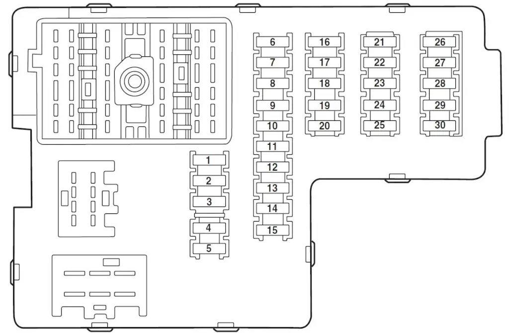
Bottom Side View of the Passenger Compartment Fuse Box
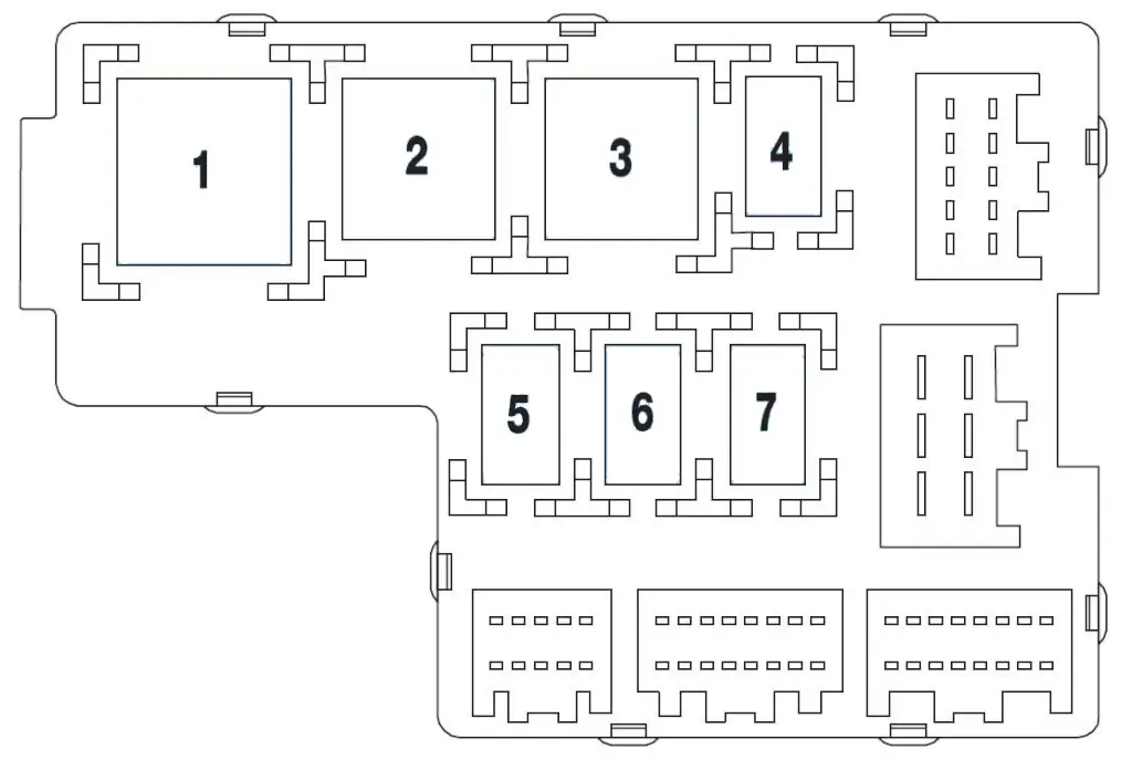
Top Side View of The Passenger Compartment Fuse Box
| Fuse Number | Amperage | Circuits Protected |
|---|---|---|
| F1 | 30 | Memory seat module, Driver power seat |
| F2 | 20 | Moonroof |
| F3 | 20 | Radio, Amplifier, DVD |
| F4 | 5 | Front wiper module |
| F5 | 15 | Flasher relay (Turn, hazards) |
| F6 | 10 | Key-in-chime |
| F7 | 15 | Heated mirrors |
| F8 | 5 | Heated PCV (4.0L engine only) |
| F9 | 15 | Not used Spare |
| F10 | 10 | Heated backlight relay coil, A/C clutch contact |
| F11 | 20 | Heated seats |
| F12 | 5 | 4x4 (switch) |
| F13 | 5 | Overdrive cancel switch |
| F14 | 5 | PATS |
| F15 | 5 | Rear wiper module, Cluster |
| F16 | 5 | Power mirror, Manual climate control, TPMS |
| F17 | 15 | Delayed accessory relay coil/Battery saver coil and contact/Reading and glove box lamps |
| F18 | 10 | Flexible fuel pump |
| F19 | 10 | Restraint Control Module (RCM) |
| F20 | 5 | Memory driver seat switch, Driver seat module, Body Security Module (BSM), PATS LED |
| F21 | 5 | Instrument cluster, Compass, Flasher coil |
| F22 | 10 | ABS, IVD Controller |
| F23 | 15 | Not used Spare |
| F24 | 15 | Cigar lighter, OBD II, Neutral tow |
| F25 | 5 | Mode-Temperature actuator for auxiliary climate control, Trailer tow battery charge relay coil, TPMS |
| F26 | 7.5 | Reverse park aid, Brake shift interlock, IVD switch |
| F27 | 7.5 | Automatic dimming mirror, Digital transmission range sensor, Backup lamps |
| F28 | 5 | Radio (Start) |
| F29 | 10 | Digital transmission range sensor, PWR feed to fuse #28 (Start feed) |
| F30 | 5 | Daytime Running Lamps (DRL), DEATC climate controller, Manual climate control, Manual climate control temp blend actuator |
| Top Side of Passenger Compartment Fuse Box | ||
| Relay 1 | Relay | Flasher |
| Relay 2 | Relay | Rear defrost |
| Relay 3 | Relay | Delayed accessory |
| Relay 4 | Relay | — |
| Relay 5 | Relay | Battery saver |
| Relay 6 | Relay | — |
| Relay 7 | Relay | — |
Location of the Emergency Fuel Pump Cut-off Switch
The switch is located in the front passenger footwell, behind the kick panel cover, near the fuse box. To reset the fuel pump shut-off switch, you’ll need to remove the access cover.
Use the following procedure to reset the fuel pump shut-off switch.
1. Turn the ignition to the OFF position.
2. Check the fuel system for leaks.
3. If no fuel leak is apparent, reset the fuel pump shut-off switch by
pushing in on the reset button.
4. Turn the ignition to the ON position. Pause for a few seconds and
return the key to the OFF position.
5. Make a further check for leaks in the fuel system.
©, 2024 Rick Muscoplat
Posted on by Rick Muscoplat